How to Use DM542: Examples, Pinouts, and Specs
Introduction
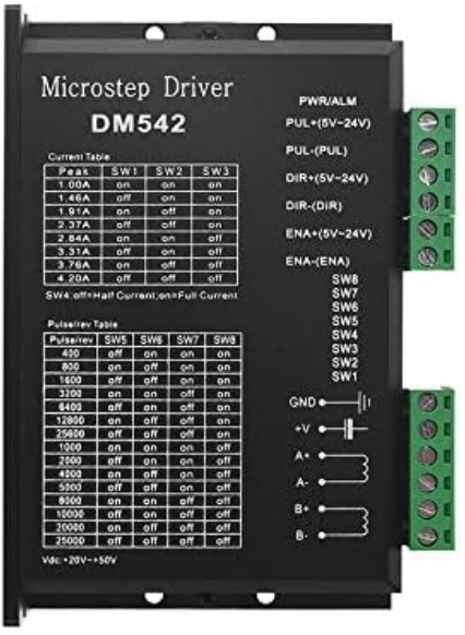
The DM542 is a digital stepper motor driver designed to provide precise control of stepper motors. It supports microstepping, enabling smoother motion and higher resolution, making it ideal for applications requiring accurate positioning and speed control. The DM542 is widely used in CNC machines, 3D printers, robotics, and other motion control systems. Its robust design and advanced features make it suitable for both industrial and hobbyist projects.
Explore Projects Built with DM542


Explore Projects Built with DM542
Technical Specifications
The DM542 stepper motor driver is designed to work with two-phase and four-phase stepper motors. Below are its key technical details:
Key Specifications
- Input Voltage: 20V to 50V DC
- Output Current: 1.0A to 4.2A (adjustable)
- Microstepping Resolution: Up to 1/128 steps
- Control Signal Voltage: 5V (compatible with TTL logic)
- Pulse Frequency: Up to 200 kHz
- Operating Temperature: -10°C to +45°C
- Protection Features: Over-voltage, under-voltage, and over-current protection
Pin Configuration and Descriptions
The DM542 has two main connectors: one for motor connections and another for control signals. Below is the pin configuration:
Motor Connector
| Pin Name | Description |
|---|---|
| A+ | Positive terminal for motor coil A |
| A- | Negative terminal for motor coil A |
| B+ | Positive terminal for motor coil B |
| B- | Negative terminal for motor coil B |
Control Signal Connector
| Pin Name | Description |
|---|---|
| PUL+ | Positive terminal for pulse signal (step input) |
| PUL- | Negative terminal for pulse signal (step input) |
| DIR+ | Positive terminal for direction signal |
| DIR- | Negative terminal for direction signal |
| ENA+ | Positive terminal for enable signal (optional, used to enable/disable driver) |
| ENA- | Negative terminal for enable signal (optional, used to enable/disable driver) |
Usage Instructions
Connecting the DM542
- Power Supply: Connect a DC power supply (20V to 50V) to the power input terminals of the DM542. Ensure the power supply can provide sufficient current for your stepper motor.
- Motor Wiring: Connect the stepper motor coils to the A+/- and B+/- terminals. Refer to your motor's datasheet to identify the correct wiring.
- Control Signals: Connect the PUL, DIR, and ENA pins to your controller (e.g., Arduino, CNC controller). Use the "+" and "-" terminals as specified in the pin configuration table.
- Microstepping and Current Settings: Use the DIP switches on the DM542 to configure the microstepping resolution and output current. Refer to the DM542 datasheet for the DIP switch settings.
Example: Connecting to an Arduino UNO
Below is an example of how to connect the DM542 to an Arduino UNO and control a stepper motor.
Wiring Diagram
- PUL+: Connect to Arduino digital pin 2
- PUL-: Connect to Arduino GND
- DIR+: Connect to Arduino digital pin 3
- DIR-: Connect to Arduino GND
- ENA+: Connect to Arduino digital pin 4 (optional)
- ENA-: Connect to Arduino GND
Arduino Code Example
// Define pin connections
#define PUL_PIN 2  // Pulse signal pin
#define DIR_PIN 3  // Direction signal pin
#define ENA_PIN 4  // Enable signal pin (optional)

void setup() {
  // Set pin modes
  pinMode(PUL_PIN, OUTPUT);
  pinMode(DIR_PIN, OUTPUT);
  pinMode(ENA_PIN, OUTPUT);

  // Enable the driver
  digitalWrite(ENA_PIN, LOW); // LOW to enable the driver
}

void loop() {
  // Set direction
  digitalWrite(DIR_PIN, HIGH); // HIGH for one direction, LOW for the other

  // Generate pulses to move the motor
  for (int i = 0; i < 200; i++) { // 200 steps for one revolution (example)
    digitalWrite(PUL_PIN, HIGH);
    delayMicroseconds(500); // Adjust for speed
    digitalWrite(PUL_PIN, LOW);
    delayMicroseconds(500); // Adjust for speed
  }

  delay(1000); // Wait 1 second before reversing direction

  // Reverse direction
  digitalWrite(DIR_PIN, LOW);

  // Generate pulses to move the motor in the opposite direction
  for (int i = 0; i < 200; i++) {
    digitalWrite(PUL_PIN, HIGH);
    delayMicroseconds(500);
    digitalWrite(PUL_PIN, LOW);
    delayMicroseconds(500);
  }

  delay(1000); // Wait 1 second before repeating
}
Important Considerations
- Power Supply: Ensure the power supply voltage and current match the requirements of both the DM542 and the stepper motor.
- Signal Timing: The pulse signal frequency determines the motor speed. Adjust the delay in the code to control the speed.
- Microstepping: Configure the DIP switches to set the desired microstepping resolution for smoother motion.
- Cooling: The DM542 may generate heat during operation. Use proper ventilation or a heatsink if necessary.
Troubleshooting and FAQs
Common Issues
Motor Not Moving:
- Check the power supply connection and ensure it is within the specified voltage range.
- Verify the motor wiring and ensure the coils are connected correctly.
- Ensure the pulse signal is being generated by the controller.
Motor Vibrates but Does Not Rotate:
- Check the direction signal (DIR) and ensure it is set correctly.
- Verify the microstepping settings on the DIP switches.
Driver Overheating:
- Ensure proper ventilation or use a heatsink.
- Check the current setting and ensure it matches the motor's rated current.
Motor Moves Erratically:
- Verify the pulse signal timing and ensure it is consistent.
- Check for loose connections in the wiring.
FAQs
Q: Can I use the DM542 with a 3.3V controller?
A: Yes, but you may need a level shifter to ensure the control signals meet the DM542's 5V logic requirements.
Q: What type of stepper motors are compatible with the DM542?
A: The DM542 is compatible with two-phase and four-phase stepper motors.
Q: How do I set the microstepping resolution?
A: Use the DIP switches on the DM542. Refer to the DM542 datasheet for the specific switch settings.
Q: Can I disable the driver when not in use?
A: Yes, use the ENA+ and ENA- pins to enable or disable the driver.
By following this documentation, you can effectively use the DM542 stepper motor driver in your projects.