How to Use pb emergency: Examples, Pinouts, and Specs
Introduction
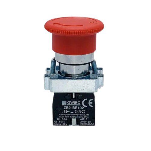
The PB Emergency is a push button switch specifically designed for emergency situations. It allows users to quickly interrupt power or activate a safety mechanism in critical scenarios. This component is commonly used in industrial machinery, safety systems, and control panels where immediate action is required to ensure safety or prevent damage.
Explore Projects Built with pb emergency


Explore Projects Built with pb emergency
Common Applications and Use Cases
- Emergency stop mechanisms in industrial equipment
- Safety shutdown systems in manufacturing plants
- Power interruption in hazardous environments
- Activation of alarms or safety protocols
- Control panels for heavy machinery
Technical Specifications
The PB Emergency switch is built to handle high-stress environments and is designed for reliability and durability. Below are the key technical details:
Key Technical Details
| Parameter | Value |
|---|---|
| Manufacturer | [Insert Manufacturer Name] |
| Part ID | [Insert Manufacturer Part ID] |
| Switch Type | Push Button (Momentary) |
| Contact Configuration | Normally Open (NO) or Normally Closed (NC) |
| Rated Voltage | 250V AC / 30V DC |
| Rated Current | 10A |
| Operating Temperature | -25°C to 70°C |
| Mechanical Durability | 1,000,000 cycles |
| Mounting Style | Panel Mount |
| Actuator Material | Polycarbonate (PC) |
| Housing Material | Flame-retardant plastic |
| IP Rating | IP65 (Dust-tight and water-resistant) |
Pin Configuration and Descriptions
The PB Emergency switch typically has two or four terminals, depending on the contact configuration (NO or NC). Below is the pin configuration:
For a 2-terminal (NO or NC) Configuration:
| Pin Number | Description |
|---|---|
| 1 | Input terminal (connect to power source or circuit) |
| 2 | Output terminal (connect to load or safety mechanism) |
For a 4-terminal (NO and NC) Configuration:
| Pin Number | Description |
|---|---|
| 1 | Normally Open (NO) input terminal |
| 2 | Normally Open (NO) output terminal |
| 3 | Normally Closed (NC) input terminal |
| 4 | Normally Closed (NC) output terminal |
Usage Instructions
The PB Emergency switch is straightforward to use but requires proper installation and wiring to ensure safety and functionality.
How to Use the Component in a Circuit
- Determine the Contact Configuration: Identify whether the switch is NO, NC, or a combination of both.
- Wiring:
- For a 2-terminal NO switch, connect the input terminal to the power source and the output terminal to the load or safety mechanism.
- For a 4-terminal switch, use the NO terminals for circuits that should activate when the button is pressed, and the NC terminals for circuits that should deactivate.
- Mounting: Secure the switch in a panel or enclosure using the provided mounting hardware. Ensure the actuator is easily accessible in case of an emergency.
- Testing: After installation, test the switch to ensure it interrupts or activates the circuit as intended.
Important Considerations and Best Practices
- Safety First: Always disconnect power before installing or wiring the switch.
- Use Proper Ratings: Ensure the voltage and current ratings of the switch match the requirements of your circuit.
- Environmental Protection: If used in harsh environments, ensure the switch's IP65 rating is sufficient or consider additional protection.
- Regular Maintenance: Periodically inspect the switch for wear and tear, especially in high-use applications.
Example: Connecting to an Arduino UNO
The PB Emergency switch can be used with an Arduino UNO to trigger an emergency stop or alarm. Below is an example circuit and code:
Circuit:
- Connect one terminal of the switch to a digital input pin (e.g., pin 2) on the Arduino.
- Connect the other terminal to the ground (GND) pin on the Arduino.
- Use a pull-up resistor (10kΩ) between the digital input pin and the 5V pin to ensure a stable signal.
Code:
// PB Emergency Switch Example with Arduino UNO
// This code monitors the PB Emergency switch and triggers an LED
// when the button is pressed (emergency condition).

const int buttonPin = 2;  // Pin connected to the PB Emergency switch
const int ledPin = 13;    // Pin connected to an LED for indication

void setup() {
  pinMode(buttonPin, INPUT_PULLUP); // Set button pin as input with pull-up resistor
  pinMode(ledPin, OUTPUT);         // Set LED pin as output
  digitalWrite(ledPin, LOW);       // Ensure LED is off initially
}

void loop() {
  int buttonState = digitalRead(buttonPin); // Read the state of the button

  if (buttonState == LOW) { // Button pressed (LOW due to pull-up resistor)
    digitalWrite(ledPin, HIGH); // Turn on the LED (emergency condition)
  } else {
    digitalWrite(ledPin, LOW);  // Turn off the LED (normal condition)
  }
}
Troubleshooting and FAQs
Common Issues Users Might Face
Switch Does Not Activate the Circuit:
- Cause: Incorrect wiring or loose connections.
- Solution: Double-check the wiring and ensure all connections are secure.
Switch Fails to Interrupt Power:
- Cause: The switch contacts may be damaged or worn out.
- Solution: Inspect the switch for physical damage and replace it if necessary.
Button Feels Stuck or Hard to Press:
- Cause: Dirt or debris may have accumulated in the actuator mechanism.
- Solution: Clean the switch with compressed air or a soft brush. Avoid using liquids.
Intermittent Operation:
- Cause: Poor contact or environmental factors (e.g., moisture).
- Solution: Ensure the switch is properly sealed and check for corrosion on the terminals.
Solutions and Tips for Troubleshooting
- Use a multimeter to test the continuity of the switch when pressed and released.
- If the switch is used in a high-vibration environment, ensure it is securely mounted to prevent accidental activation.
- For Arduino applications, verify the pull-up resistor is correctly connected to avoid false readings.
By following this documentation, users can effectively integrate and maintain the PB Emergency switch in their systems, ensuring reliable performance in critical situations.