
How to Use Solar charge controller: Examples, Pinouts, and Specs
 Design with Solar charge controller in Cirkit Designer
Introduction
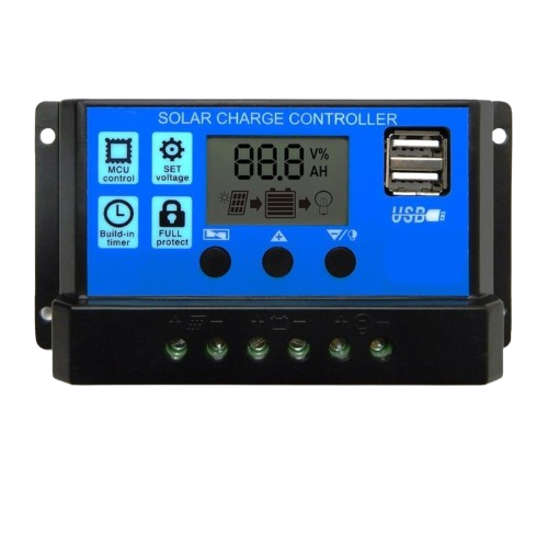
A solar charge controller is a critical component in solar power systems. It regulates the voltage and current coming from a solar panel to a battery, ensuring optimal charging and preventing overcharging. By managing the energy flow, it protects the battery from damage and extends its lifespan. Solar charge controllers are commonly used in off-grid solar systems, RVs, boats, and remote power setups.
Explore Projects Built with Solar charge controller
 Open Project in Cirkit Designer
 Open Project in Cirkit Designer
 Open Project in Cirkit Designer
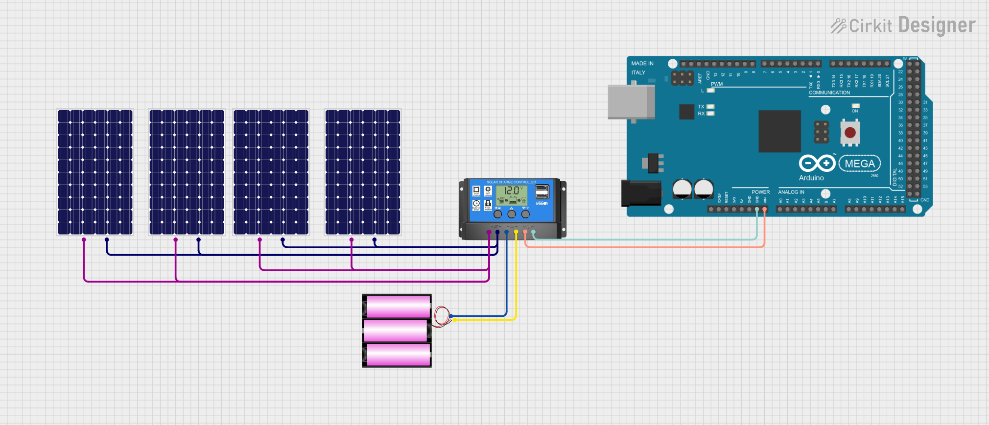 Open Project in Cirkit Designer
Explore Projects Built with Solar charge controller
Open Project in Cirkit DesignerOpen Project in Cirkit DesignerOpen Project in Cirkit DesignerOpen Project in Cirkit DesignerCommon Applications and Use Cases
- Off-grid solar power systems
- Solar-powered lighting systems
- RVs, boats, and caravans
- Remote monitoring stations
- Backup power systems
Technical Specifications
Below are the general technical specifications for a typical solar charge controller. Always refer to the specific datasheet for your model.
Key Technical Details
- Input Voltage Range: 12V/24V auto-detect (some models support up to 48V)
- Maximum Input Current: 10A, 20A, 30A, or higher (depending on the model)
- Battery Voltage: 12V/24V (auto-detect)
- Charging Technology: PWM (Pulse Width Modulation) or MPPT (Maximum Power Point Tracking)
- Operating Temperature: -20°C to +60°C
- Efficiency: Up to 98% (for MPPT models)
- Load Control: Overload and short-circuit protection
- Display: LCD or LED indicators for system status
Pin Configuration and Descriptions
The solar charge controller typically has the following terminals:
| Pin/Terminal | Label | Description |
|---|---|---|
| 1 | Solar Panel (+) | Positive terminal for connecting the solar panel. |
| 2 | Solar Panel (-) | Negative terminal for connecting the solar panel. |
| 3 | Battery (+) | Positive terminal for connecting the battery. |
| 4 | Battery (-) | Negative terminal for connecting the battery. |
| 5 | Load (+) | Positive terminal for connecting the DC load (e.g., lights, fans). |
| 6 | Load (-) | Negative terminal for connecting the DC load. |
| 7 | Ground (GND) | Optional grounding terminal for safety and noise reduction (if available). |
| 8 | Communication | Optional communication port (e.g., RS485, USB) for monitoring and configuration. |
Usage Instructions
How to Use the Solar Charge Controller in a Circuit
Connect the Battery First:
- Connect the positive and negative terminals of the battery to the corresponding battery terminals on the charge controller.
- Ensure the battery voltage matches the controller's supported range (e.g., 12V or 24V).
Connect the Solar Panel:
- Connect the positive and negative terminals of the solar panel to the solar input terminals on the charge controller.
- Ensure the solar panel's voltage and current are within the controller's input range.
Connect the Load (Optional):
- If you want to power DC devices directly, connect the load to the load terminals on the charge controller.
- Ensure the load does not exceed the controller's rated output current.
Power On:
- The charge controller will automatically detect the system voltage and begin operation.
- Check the display or indicators for system status.
Important Considerations and Best Practices
- Battery Type: Ensure the charge controller is compatible with your battery type (e.g., lead-acid, lithium-ion).
- Wiring: Use appropriately sized wires to handle the current without overheating.
- Fuses: Install fuses or circuit breakers between the solar panel, battery, and controller for safety.
- Ventilation: Place the charge controller in a well-ventilated area to prevent overheating.
- Waterproofing: If used outdoors, ensure the controller is rated for outdoor use or housed in a waterproof enclosure.
Arduino Integration Example
Some advanced solar charge controllers support communication protocols like RS485 or UART, allowing integration with microcontrollers like Arduino for monitoring. Below is an example of how to read data from a solar charge controller using Modbus RTU over RS485.
#include <ModbusMaster.h>

// Create an instance of the ModbusMaster library
ModbusMaster node;

// Define the RS485 communication pins
#define RE_PIN 2  // Receiver Enable pin
#define DE_PIN 3  // Driver Enable pin

void preTransmission() {
  digitalWrite(RE_PIN, HIGH); // Enable transmission
  digitalWrite(DE_PIN, HIGH);
}

void postTransmission() {
  digitalWrite(RE_PIN, LOW);  // Disable transmission
  digitalWrite(DE_PIN, LOW);
}

void setup() {
  Serial.begin(9600);         // Initialize serial communication
  pinMode(RE_PIN, OUTPUT);    // Set RE pin as output
  pinMode(DE_PIN, OUTPUT);    // Set DE pin as output

  // Initialize Modbus communication
  node.begin(1, Serial);      // Set Modbus slave ID to 1
  node.preTransmission(preTransmission);
  node.postTransmission(postTransmission);
}

void loop() {
  uint8_t result;
  uint16_t data;

  // Read battery voltage (example register address: 0x3100)
  result = node.readInputRegisters(0x3100, 1);
  if (result == node.ku8MBSuccess) {
    data = node.getResponseBuffer(0);
    Serial.print("Battery Voltage: ");
    Serial.print(data / 100.0); // Convert to volts
    Serial.println(" V");
  } else {
    Serial.println("Failed to read data");
  }

  delay(1000); // Wait 1 second before the next read
}
Troubleshooting and FAQs
Common Issues and Solutions
No Power or Controller Not Turning On:
- Check the battery connection. The controller typically requires a battery to power on.
- Verify that the battery voltage is within the supported range.
Solar Panel Not Charging the Battery:
- Ensure the solar panel is receiving sufficient sunlight.
- Check the wiring between the solar panel and the controller.
- Verify that the solar panel's voltage and current are within the controller's input range.
Load Not Powering On:
- Ensure the load is connected to the correct terminals.
- Check if the load exceeds the controller's rated output current.
- Verify that the controller's load output is enabled (some models allow manual control).
Overheating:
- Ensure the controller is installed in a well-ventilated area.
- Check for loose or undersized wiring that may cause excessive heat.
FAQs
Q: Can I use the solar charge controller without a battery?
A: Most solar charge controllers require a battery to function properly. Some advanced models may support direct load operation without a battery, but this is not common.Q: What is the difference between PWM and MPPT controllers?
A: PWM controllers are simpler and less expensive but less efficient. MPPT controllers are more advanced and can extract maximum power from the solar panel, especially in varying sunlight conditions.Q: How do I know if my battery is fully charged?
A: Most controllers have indicators or displays that show the battery's charge status. Refer to the user manual for specific details.Q: Can I connect multiple solar panels to one controller?
A: Yes, but ensure the combined voltage and current of the panels do not exceed the controller's input limits. Use series or parallel connections as appropriate.
This concludes the documentation for the solar charge controller. Always refer to the manufacturer's datasheet for specific details about your model.