How to Use HiLetGo ESP-32: Examples, Pinouts, and Specs
Introduction
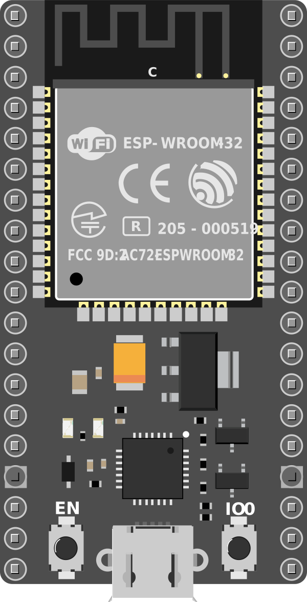
The HiLetGo ESP-32 is a versatile and powerful microcontroller development board that leverages the capabilities of the ESP32 chip. This board is widely used in the Internet of Things (IoT) projects due to its integrated Bluetooth and WiFi functionalities. It is suitable for a variety of applications, including smart home devices, wireless sensors, and other connected gadgets.
Explore Projects Built with HiLetGo ESP-32
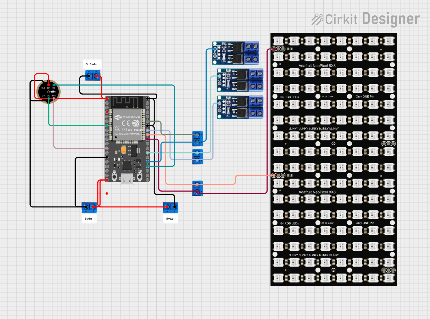


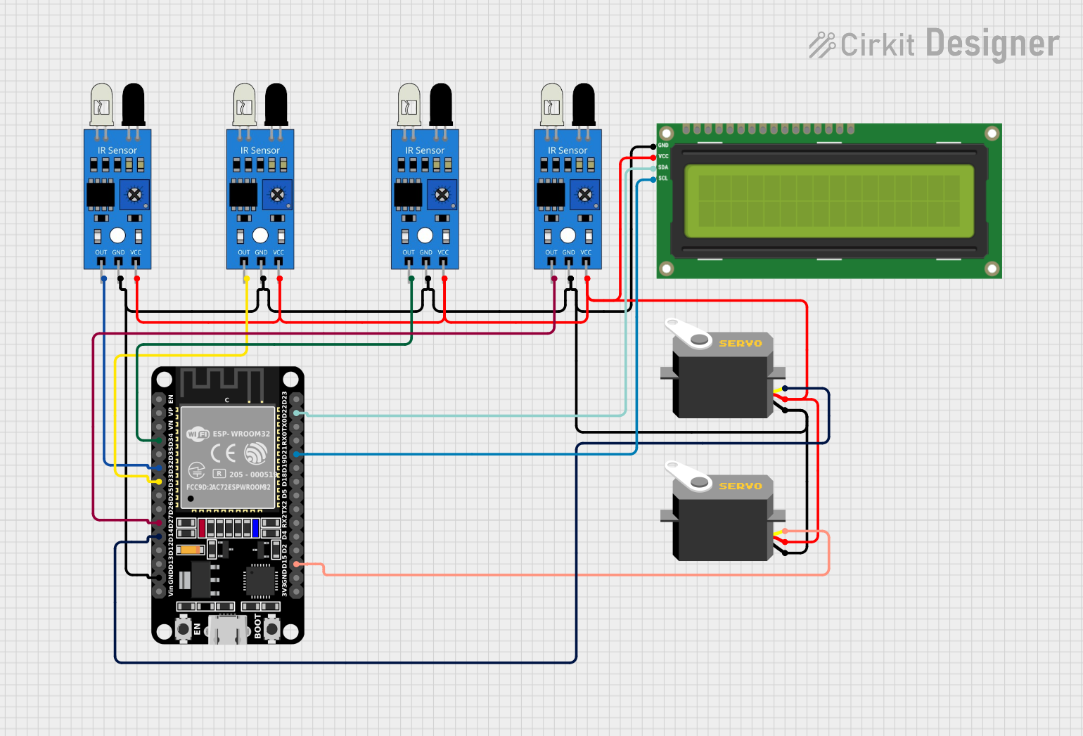
Explore Projects Built with HiLetGo ESP-32
Technical Specifications
Key Features
- Microcontroller: ESP32-D0WDQ6
- Operating Voltage: 3.3V
- Digital I/O Pins: 22
- Analog Input Pins: 6 (ADC, up to 12-bit resolution)
- Analog Output Pins: 2 (DAC, 8-bit resolution)
- Flash Memory: 4MB
- SRAM: 520 KB
- Clock Speed: Up to 240MHz
- Integrated WiFi: 802.11 b/g/n
- Integrated Bluetooth: v4.2 BR/EDR and BLE
- Temperature Range: -40°C to +125°C
Pin Configuration
| Pin Number | Function | Description |
|---|---|---|
| 1 | 3V3 | 3.3V power supply input |
| 2 | GND | Ground |
| 3-18 | GPIO0 - GPIO15 | General-purpose input/output pins |
| 19 | ADC1_CH0 - CH5 | Analog-to-digital converter channels 0 to 5 |
| 20 | DAC1, DAC2 | Digital-to-analog converter channels 1 and 2 |
| 21 | EN | Chip enable, active high |
| 22 | VIN | Voltage input for battery or unregulated power supply |
Usage Instructions
Basic Setup
To use the HiLetGo ESP-32 in a circuit:
- Connect the
3V3pin to a 3.3V power supply. - Connect the
GNDpin to the ground of the power supply. - Use the GPIO pins for digital input/output as required by your application.
- If analog input is needed, connect sensors to the ADC pins.
- For analog output, utilize the DAC pins.
Programming
The ESP-32 can be programmed using the Arduino IDE or other development environments that support the ESP32 platform. To program the board:
- Install the ESP32 board package in the Arduino IDE.
- Select the correct board and port in the Arduino IDE.
- Write your code and upload it to the board.
Example Code
Here is a simple example of how to blink an LED using the ESP-32 and Arduino IDE:
// Define the LED pin
const int LED_PIN = 2; // Use GPIO2 for the built-in LED

void setup() {
  // Initialize the LED pin as an output
  pinMode(LED_PIN, OUTPUT);
}

void loop() {
  // Turn the LED on
  digitalWrite(LED_PIN, HIGH);
  delay(1000); // Wait for a second
  // Turn the LED off
  digitalWrite(LED_PIN, LOW);
  delay(1000); // Wait for a second
}
Ensure that your code comments are concise and do not exceed 80 characters in line length.
Troubleshooting and FAQs
Common Issues
- Board not detected: Ensure that the USB drivers are installed and the board is selected in the Arduino IDE.
- WiFi or Bluetooth not functioning: Check that the antennas are properly connected and that the correct libraries are included in your code.
- Unexpected resets: This can be caused by insufficient power supply. Make sure that the power source can deliver enough current.
FAQs
Q: Can the ESP-32 be powered by batteries?
A: Yes, the ESP-32 can be powered by batteries connected to the VIN pin.
Q: How do I connect to WiFi using the ESP-32?
A: Use the WiFi.h library in your Arduino code to connect to WiFi networks.
Q: What is the maximum current that the GPIO pins can handle? A: Each GPIO pin can source or sink up to 12 mA.
Q: How can I save power when running on batteries? A: Utilize the ESP32's deep sleep mode to significantly reduce power consumption when the device is not active.
For further assistance, consult the ESP32 datasheet and the HiLetGo ESP-32 forums for community support.