
How to Use OEP50Wx2: Examples, Pinouts, and Specs
 Design with OEP50Wx2 in Cirkit Designer
Introduction
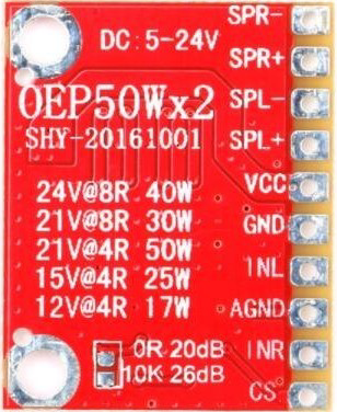
The OEP50Wx2 is a dual-channel audio transformer designed for high-fidelity audio applications. Manufactured by Sunhokey, this component provides excellent isolation and impedance matching between audio devices, ensuring minimal signal distortion and optimal audio quality. It is particularly suited for use in audio amplifiers, mixers, and other professional audio equipment.
Explore Projects Built with OEP50Wx2
 Open Project in Cirkit Designer
 Open Project in Cirkit Designer
 Open Project in Cirkit Designer
 Open Project in Cirkit Designer
Explore Projects Built with OEP50Wx2
Open Project in Cirkit DesignerOpen Project in Cirkit DesignerOpen Project in Cirkit DesignerOpen Project in Cirkit DesignerCommon Applications and Use Cases
- High-fidelity audio systems
- Audio signal isolation and noise reduction
- Impedance matching between audio devices
- Professional audio mixers and amplifiers
- Home theater systems
Technical Specifications
Below are the key technical details for the OEP50Wx2:
| Parameter | Value |
|---|---|
| Manufacturer | Sunhokey |
| Part ID | 50W+50W Dual Channel Class D Digital Audio Power Amplifier Board |
| Channels | 2 (Dual Channel) |
| Power Output | 50W per channel |
| Frequency Response | 20 Hz – 20 kHz |
| Impedance | 4–8 Ω |
| Signal-to-Noise Ratio (SNR) | ≥ 90 dB |
| Total Harmonic Distortion | ≤ 0.1% |
| Input Voltage | 12V–24V DC |
| Dimensions | 100 mm x 60 mm x 20 mm |
| Weight | 80 g |
Pin Configuration and Descriptions
The OEP50Wx2 features the following pin configuration:
| Pin Name | Description |
|---|---|
| VIN+ | Positive DC power input (12V–24V) |
| GND | Ground connection |
| L_IN | Left channel audio input |
| R_IN | Right channel audio input |
| L_OUT+ | Positive output for the left audio channel |
| L_OUT- | Negative output for the left audio channel |
| R_OUT+ | Positive output for the right audio channel |
| R_OUT- | Negative output for the right audio channel |
Usage Instructions
How to Use the Component in a Circuit
- Power Supply: Connect a DC power source (12V–24V) to the
VIN+andGNDpins. Ensure the power supply can provide sufficient current for the amplifier's operation. - Audio Input: Connect the left and right audio signals to the
L_INandR_INpins, respectively. Use shielded cables to minimize noise. - Audio Output: Connect the left and right speakers to the
L_OUT+,L_OUT-,R_OUT+, andR_OUT-pins. Ensure the speakers have an impedance of 4–8 Ω. - Heat Dissipation: The amplifier may generate heat during operation. Attach a heatsink or ensure proper ventilation to prevent overheating.
Important Considerations and Best Practices
- Power Supply: Use a stable and noise-free DC power supply to avoid introducing hum or noise into the audio signal.
- Speaker Impedance: Ensure the connected speakers match the recommended impedance range (4–8 Ω) to prevent damage to the amplifier.
- Signal Grounding: Properly ground the audio input and output connections to minimize noise and interference.
- Volume Control: Use a preamplifier or volume control circuit to adjust the input signal level before feeding it into the amplifier.
Example: Connecting to an Arduino UNO
The OEP50Wx2 can be used with an Arduino UNO to create a simple audio playback system. Below is an example of how to generate a PWM audio signal using the Arduino and feed it into the amplifier:
/*
  Example: Generating a PWM audio signal for the OEP50Wx2 amplifier
  This code generates a simple square wave audio signal on pin 9.
  Connect pin 9 to the L_IN or R_IN pin of the amplifier.
*/

const int audioPin = 9; // PWM output pin for audio signal

void setup() {
  pinMode(audioPin, OUTPUT); // Set the audio pin as an output
}

void loop() {
  // Generate a square wave at 1 kHz
  digitalWrite(audioPin, HIGH); // Set the pin HIGH
  delayMicroseconds(500);       // Wait for 500 microseconds (1 kHz frequency)
  digitalWrite(audioPin, LOW);  // Set the pin LOW
  delayMicroseconds(500);       // Wait for 500 microseconds
}
Note: This example generates a basic square wave signal. For high-quality audio playback, consider using an external DAC or audio shield with the Arduino.
Troubleshooting and FAQs
Common Issues Users Might Face
No Audio Output:
- Cause: Incorrect wiring or loose connections.
- Solution: Double-check all connections, especially the input and output pins.
Distorted Audio:
- Cause: Input signal level is too high or speakers have incorrect impedance.
- Solution: Reduce the input signal level or use speakers with the recommended impedance (4–8 Ω).
Overheating:
- Cause: Insufficient heat dissipation or excessive power draw.
- Solution: Attach a heatsink to the amplifier or improve ventilation.
Noise or Hum:
- Cause: Poor grounding or noisy power supply.
- Solution: Use a clean, stable power supply and ensure proper grounding of all connections.
Solutions and Tips for Troubleshooting
- Use a multimeter to verify the voltage at the
VIN+andGNDpins. - Test the audio input signal with an oscilloscope to ensure it is within the acceptable range.
- If the amplifier shuts down unexpectedly, check for short circuits or excessive current draw.
By following this documentation, users can effectively integrate the OEP50Wx2 into their audio systems and troubleshoot common issues with ease.