How to Use XL4016E1: Examples, Pinouts, and Specs
Introduction
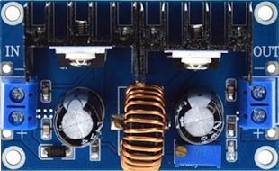
The XL4016E1 is a high-performance step-down (buck) voltage regulator designed to efficiently convert a higher input voltage to a lower, stable output voltage. It is capable of delivering up to 8A of output current, making it ideal for applications requiring high current and adjustable voltage. The XL4016E1 features high efficiency, adjustable output voltage, and built-in protection mechanisms such as overcurrent protection and thermal shutdown. These features make it a reliable choice for power supply circuits, battery chargers, LED drivers, and other DC-DC conversion applications.
Explore Projects Built with XL4016E1


Explore Projects Built with XL4016E1
Common Applications
- Adjustable DC power supplies
- Battery charging circuits
- LED lighting systems
- Motor drivers
- Embedded systems requiring regulated power
Technical Specifications
The following table outlines the key technical specifications of the XL4016E1:
| Parameter | Value |
|---|---|
| Input Voltage Range | 5V to 40V |
| Output Voltage Range | 1.25V to 36V (adjustable) |
| Maximum Output Current | 8A |
| Efficiency | Up to 95% |
| Switching Frequency | 180 kHz |
| Operating Temperature | -40°C to +85°C |
| Protection Features | Overcurrent, thermal shutdown |
Pin Configuration and Descriptions
The XL4016E1 is typically available in a TO-220-5L package. The pin configuration is as follows:
| Pin Number | Pin Name | Description |
|---|---|---|
| 1 | VIN | Input voltage (5V to 40V). Connect to the power source. |
| 2 | GND | Ground. Connect to the circuit ground. |
| 3 | VOUT | Regulated output voltage (1.25V to 36V). |
| 4 | FB | Feedback pin. Used to set the output voltage via a resistor divider. |
| 5 | EN | Enable pin. High to enable the regulator, low to disable. |
Usage Instructions
How to Use the XL4016E1 in a Circuit
- Input Voltage: Connect the input voltage (5V to 40V) to the VIN pin. Ensure the input voltage is higher than the desired output voltage by at least 1.5V for proper regulation.
- Output Voltage Adjustment: Use a resistor divider network connected to the FB pin to set the desired output voltage. The output voltage can be calculated using the formula: [ V_{OUT} = 1.25 \times \left(1 + \frac{R1}{R2}\right) ] where R1 and R2 are the resistors in the feedback network.
- Enable Pin: Connect the EN pin to a high logic level (e.g., VIN) to enable the regulator. Pull it low to disable the output.
- Output Capacitor: Place a suitable capacitor (e.g., 100µF) at the output to stabilize the voltage and reduce ripple.
- Heat Dissipation: Since the XL4016E1 can handle high currents, ensure proper heat dissipation using a heatsink or active cooling if necessary.
Example: Using XL4016E1 with Arduino UNO
The XL4016E1 can be used to power an Arduino UNO by stepping down a higher voltage (e.g., 12V) to 5V. Below is an example circuit and Arduino code to monitor the output voltage.
Circuit Connections
- Connect a 12V power source to the VIN pin of the XL4016E1.
- Adjust the feedback resistors to set the output voltage to 5V.
- Connect the VOUT pin to the Arduino UNO's 5V input pin.
- Connect the GND pin to the Arduino's ground.
Arduino Code
// This code reads the output voltage of the XL4016E1 using an analog pin
// and displays the voltage on the serial monitor.

const int voltagePin = A0; // Analog pin connected to the output voltage
const float referenceVoltage = 5.0; // Arduino reference voltage (5V)
const float voltageDividerRatio = 5.7; // Adjust based on your resistor divider

void setup() {
  Serial.begin(9600); // Initialize serial communication
  pinMode(voltagePin, INPUT); // Set the voltage pin as input
}

void loop() {
  int analogValue = analogRead(voltagePin); // Read the analog value
  float outputVoltage = (analogValue * referenceVoltage / 1023.0)
                        * voltageDividerRatio; // Calculate the voltage

  Serial.print("Output Voltage: ");
  Serial.print(outputVoltage);
  Serial.println(" V");

  delay(1000); // Wait for 1 second before the next reading
}
Important Considerations
- Input Voltage: Ensure the input voltage is within the specified range (5V to 40V).
- Heat Management: Use a heatsink or active cooling for high-current applications to prevent overheating.
- Output Capacitor: Use low-ESR capacitors to minimize output voltage ripple.
- Feedback Resistors: Choose precise resistors for accurate output voltage adjustment.
Troubleshooting and FAQs
Common Issues and Solutions
No Output Voltage
- Cause: The EN pin is not connected or is pulled low.
- Solution: Ensure the EN pin is connected to a high logic level (e.g., VIN).
Output Voltage is Incorrect
- Cause: Incorrect feedback resistor values.
- Solution: Verify the resistor values and recalculate the output voltage using the formula.
Overheating
- Cause: High current draw without proper heat dissipation.
- Solution: Attach a heatsink or use active cooling to manage heat.
High Output Ripple
- Cause: Insufficient or poor-quality output capacitor.
- Solution: Use a low-ESR capacitor with a higher capacitance value.
FAQs
Q1: Can the XL4016E1 be used for battery charging?
Yes, the XL4016E1 can be used for battery charging applications. However, ensure the output voltage and current are set according to the battery's specifications.
Q2: What is the maximum efficiency of the XL4016E1?
The XL4016E1 can achieve an efficiency of up to 95%, depending on the input voltage, output voltage, and load conditions.
Q3: Can I use the XL4016E1 without a heatsink?
For low-current applications, a heatsink may not be necessary. However, for high-current applications (e.g., above 5A), a heatsink or active cooling is recommended to prevent thermal shutdown.
Q4: How do I calculate the feedback resistor values?
Use the formula:
[
V_{OUT} = 1.25 \times \left(1 + \frac{R1}{R2}\right)
]
where R1 is connected between VOUT and FB, and R2 is connected between FB and GND.
By following this documentation, you can effectively integrate the XL4016E1 into your projects and troubleshoot common issues.