How to Use Adafruit MCP23017 I2C GPIO Expander Breakout: Examples, Pinouts, and Specs
Introduction
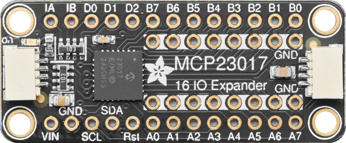
The Adafruit MCP23017 I2C GPIO Expander Breakout (Part ID: 5346) is a versatile component that provides 16 additional General Purpose Input/Output (GPIO) pins via I2C communication. This breakout board is ideal for expanding the input/output capabilities of microcontroller projects, such as those using Arduino, Raspberry Pi, or other development platforms. It allows for easy integration and control of multiple devices, sensors, and actuators without the need for additional microcontroller pins.
Explore Projects Built with Adafruit MCP23017 I2C GPIO Expander Breakout


Explore Projects Built with Adafruit MCP23017 I2C GPIO Expander Breakout
Common Applications and Use Cases
- Home Automation: Control multiple relays, lights, and sensors.
- Robotics: Manage multiple sensors, motors, and actuators.
- IoT Projects: Expand the number of input/output devices connected to a single microcontroller.
- Prototyping: Quickly add more GPIO pins for testing and development.
Technical Specifications
Key Technical Details
| Parameter | Value |
|---|---|
| Operating Voltage | 1.8V to 5.5V |
| I2C Address Range | 0x20 to 0x27 (configurable) |
| GPIO Pins | 16 (split into two 8-bit ports) |
| Maximum Current | 25mA per pin |
| Package Type | DIP |
| Communication | I2C |
Pin Configuration and Descriptions
| Pin Number | Pin Name | Description |
|---|---|---|
| 1 | GPA0 | GPIO Port A Pin 0 |
| 2 | GPA1 | GPIO Port A Pin 1 |
| 3 | GPA2 | GPIO Port A Pin 2 |
| 4 | GPA3 | GPIO Port A Pin 3 |
| 5 | GPA4 | GPIO Port A Pin 4 |
| 6 | GPA5 | GPIO Port A Pin 5 |
| 7 | GPA6 | GPIO Port A Pin 6 |
| 8 | GPA7 | GPIO Port A Pin 7 |
| 9 | GPB0 | GPIO Port B Pin 0 |
| 10 | GPB1 | GPIO Port B Pin 1 |
| 11 | GPB2 | GPIO Port B Pin 2 |
| 12 | GPB3 | GPIO Port B Pin 3 |
| 13 | GPB4 | GPIO Port B Pin 4 |
| 14 | GPB5 | GPIO Port B Pin 5 |
| 15 | GPB6 | GPIO Port B Pin 6 |
| 16 | GPB7 | GPIO Port B Pin 7 |
| 17 | VDD | Power Supply (1.8V to 5.5V) |
| 18 | VSS | Ground |
| 19 | SCL | I2C Clock Line |
| 20 | SDA | I2C Data Line |
| 21 | RESET | Reset (Active Low) |
| 22 | A0 | I2C Address Selection Bit 0 |
| 23 | A1 | I2C Address Selection Bit 1 |
| 24 | A2 | I2C Address Selection Bit 2 |
| 25 | INTA | Interrupt Output for Port A |
| 26 | INTB | Interrupt Output for Port B |
Usage Instructions
How to Use the Component in a Circuit
- Power Supply: Connect the VDD pin to a power supply (1.8V to 5.5V) and the VSS pin to ground.
- I2C Communication: Connect the SCL pin to the I2C clock line and the SDA pin to the I2C data line of your microcontroller.
- Address Configuration: Set the I2C address by connecting the A0, A1, and A2 pins to either VDD or VSS. The default address is 0x20.
- GPIO Connections: Connect your devices to the GPA0-GPA7 and GPB0-GPB7 pins as needed.
- Interrupts (Optional): Connect the INTA and INTB pins to your microcontroller if you want to use interrupt functionality.
Important Considerations and Best Practices
- Pull-up Resistors: Ensure that the I2C lines (SCL and SDA) have appropriate pull-up resistors (typically 4.7kΩ).
- Current Limiting: Do not exceed the maximum current rating of 25mA per GPIO pin.
- Address Conflicts: Avoid address conflicts by ensuring that each I2C device on the bus has a unique address.
- Debouncing: Implement software debouncing for input pins to avoid false triggers.
Example Code for Arduino UNO
#include <Wire.h>
#include "Adafruit_MCP23017.h"

// Create an instance of the MCP23017 class
Adafruit_MCP23017 mcp;

void setup() {
  // Initialize the I2C communication
  Wire.begin();

  // Initialize the MCP23017
  mcp.begin();      // Default address 0x20

  // Set GPA0 as an output pin
  mcp.pinMode(0, OUTPUT);

  // Set GPB0 as an input pin with pull-up resistor
  mcp.pinMode(8, INPUT);
  mcp.pullUp(8, HIGH);

  // Start serial communication for debugging
  Serial.begin(9600);
}

void loop() {
  // Read the state of GPB0
  uint8_t buttonState = mcp.digitalRead(8);

  // If the button is pressed, turn on the LED connected to GPA0
  if (buttonState == LOW) {
    mcp.digitalWrite(0, HIGH);
  } else {
    mcp.digitalWrite(0, LOW);
  }

  // Print the button state to the serial monitor
  Serial.println(buttonState);

  // Small delay to avoid bouncing issues
  delay(50);
}
Troubleshooting and FAQs
Common Issues Users Might Face
I2C Communication Failure:
- Solution: Check the connections for SCL and SDA lines. Ensure pull-up resistors are in place.
Incorrect GPIO Behavior:
- Solution: Verify the pinMode and digitalWrite/digitalRead configurations in your code.
Address Conflicts:
- Solution: Ensure that each I2C device on the bus has a unique address. Adjust the A0, A1, and A2 pins accordingly.
Overcurrent on GPIO Pins:
- Solution: Ensure that the current drawn by each GPIO pin does not exceed 25mA. Use current-limiting resistors if necessary.
Solutions and Tips for Troubleshooting
- Check Connections: Ensure all connections are secure and correctly placed.
- Use a Multimeter: Measure voltages and continuity to diagnose connection issues.
- Consult Datasheets: Refer to the MCP23017 datasheet for detailed technical information.
- Update Libraries: Ensure you are using the latest version of the Adafruit MCP23017 library.
By following this documentation, users can effectively integrate and utilize the Adafruit MCP23017 I2C GPIO Expander Breakout in their projects, expanding their microcontroller's input/output capabilities with ease.