Cirkit Designer Logo
Cirkit Designer
Your all-in-one circuit design IDE
Home / 
Component Documentation

How to Use PCM1052A: Examples, Pinouts, and Specs

Image of PCM1052A
Cirkit Designer LogoDesign with PCM1052A in Cirkit Designer

Introduction

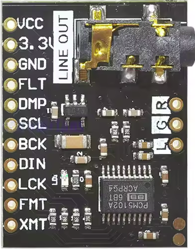
The PCM5102A DAC Decoder Board is a high-performance, low-power, 24-bit stereo audio digital-to-analog converter (DAC) designed for audio applications. Manufactured by diymore, this component boasts a dynamic range of 105 dB and supports sampling rates up to 192 kHz. It is ideal for applications requiring high-quality audio output, such as digital audio players, home theater systems, and audio interfaces.

Explore Projects Built with PCM1052A

Use Cirkit Designer to design, explore, and prototype these projects online. Some projects support real-time simulation. Click "Open Project" to start designing instantly!
Battery-Powered MP3 Player with Amplified Dual Speakers
Image of bluethooth speaker( 2 speaker): A project utilizing PCM1052A in a practical application
This circuit is a portable audio playback system powered by two 18650 Li-ion batteries, which are charged and protected by a TP4056 module. The MP3 module provides audio signals to a 5V amplifier board, which then drives two speakers. A push switch is used to control the power to the MP3 module and amplifier.
Cirkit Designer LogoOpen Project in Cirkit Designer
Battery-Powered Raspberry Pi Pico GPS Tracker with Sensor Integration
Image of Copy of CanSet v1: A project utilizing PCM1052A in a practical application
This circuit is a data acquisition and communication system powered by a LiPoly battery and managed by a Raspberry Pi Pico. It includes sensors (BMP280, MPU9250) for environmental data, a GPS module for location tracking, an SD card for data storage, and a WLR089-CanSAT for wireless communication. The TP4056 module handles battery charging, and a toggle switch controls power distribution.
Cirkit Designer LogoOpen Project in Cirkit Designer
Bluetooth Audio Receiver with Battery-Powered Amplifier and Loudspeakers
Image of speaker bluetooh portable: A project utilizing PCM1052A in a practical application
This circuit is a Bluetooth-enabled audio system powered by a rechargeable 18650 Li-ion battery. It includes a TP4056 module for battery charging and protection, a PAM8403 amplifier with volume control to drive two loudspeakers, and a Bluetooth audio receiver to wirelessly receive audio signals.
Cirkit Designer LogoOpen Project in Cirkit Designer
ESP32-Powered Wi-Fi Controlled Robotic Car with OLED Display and Ultrasonic Sensor
Image of playbot: A project utilizing PCM1052A in a practical application
This circuit is a battery-powered system featuring an ESP32 microcontroller that controls an OLED display, a motor driver for two hobby motors, an ultrasonic sensor for distance measurement, and a DFPlayer Mini for audio output through a loudspeaker. The TP4056 module manages battery charging, and a step-up boost converter provides a stable 5V supply to the components.
Cirkit Designer LogoOpen Project in Cirkit Designer

Explore Projects Built with PCM1052A

Use Cirkit Designer to design, explore, and prototype these projects online. Some projects support real-time simulation. Click "Open Project" to start designing instantly!
Image of bluethooth speaker( 2 speaker): A project utilizing PCM1052A in a practical application
Battery-Powered MP3 Player with Amplified Dual Speakers
This circuit is a portable audio playback system powered by two 18650 Li-ion batteries, which are charged and protected by a TP4056 module. The MP3 module provides audio signals to a 5V amplifier board, which then drives two speakers. A push switch is used to control the power to the MP3 module and amplifier.
Cirkit Designer LogoOpen Project in Cirkit Designer
Image of Copy of CanSet v1: A project utilizing PCM1052A in a practical application
Battery-Powered Raspberry Pi Pico GPS Tracker with Sensor Integration
This circuit is a data acquisition and communication system powered by a LiPoly battery and managed by a Raspberry Pi Pico. It includes sensors (BMP280, MPU9250) for environmental data, a GPS module for location tracking, an SD card for data storage, and a WLR089-CanSAT for wireless communication. The TP4056 module handles battery charging, and a toggle switch controls power distribution.
Cirkit Designer LogoOpen Project in Cirkit Designer
Image of speaker bluetooh portable: A project utilizing PCM1052A in a practical application
Bluetooth Audio Receiver with Battery-Powered Amplifier and Loudspeakers
This circuit is a Bluetooth-enabled audio system powered by a rechargeable 18650 Li-ion battery. It includes a TP4056 module for battery charging and protection, a PAM8403 amplifier with volume control to drive two loudspeakers, and a Bluetooth audio receiver to wirelessly receive audio signals.
Cirkit Designer LogoOpen Project in Cirkit Designer
Image of playbot: A project utilizing PCM1052A in a practical application
ESP32-Powered Wi-Fi Controlled Robotic Car with OLED Display and Ultrasonic Sensor
This circuit is a battery-powered system featuring an ESP32 microcontroller that controls an OLED display, a motor driver for two hobby motors, an ultrasonic sensor for distance measurement, and a DFPlayer Mini for audio output through a loudspeaker. The TP4056 module manages battery charging, and a step-up boost converter provides a stable 5V supply to the components.
Cirkit Designer LogoOpen Project in Cirkit Designer

Technical Specifications

Key Technical Details

Parameter Value
Manufacturer diymore
Part ID PCM5102A DAC Decoder Board
Resolution 24-bit
Dynamic Range 105 dB
Sampling Rate Up to 192 kHz
Power Supply Voltage 3.3V to 5V
Interface I2S, IIC
Output Type Stereo Analog
Power Consumption Low Power

Pin Configuration and Descriptions

Pin Number Pin Name Description
1 GND Ground
2 VCC Power Supply (3.3V to 5V)
3 LRCK Left/Right Clock (I2S Interface)
4 BCK Bit Clock (I2S Interface)
5 DATA Serial Data Input (I2S Interface)
6 SCL Serial Clock Line (IIC Interface)
7 SDA Serial Data Line (IIC Interface)
8 FMT Format Selection (I2S/IIC)
9 XSMT Mute Control
10 FLT Filter Selection
11 SCK System Clock
12 GND Ground

Usage Instructions

How to Use the Component in a Circuit

  1. Power Supply: Connect the VCC pin to a 3.3V or 5V power supply and the GND pin to the ground.
  2. I2S Interface: Connect the LRCK, BCK, and DATA pins to the corresponding pins on your microcontroller or audio source.
  3. IIC Interface: Connect the SCL and SDA pins to the IIC bus of your microcontroller.
  4. Control Pins: Use the FMT pin to select the desired data format (I2S or IIC). The XSMT pin can be used to mute the output, and the FLT pin can be used to select the filter type.
  5. System Clock: Connect the SCK pin to the system clock source.

Important Considerations and Best Practices

  • Ensure that the power supply voltage is within the specified range (3.3V to 5V).
  • Use proper decoupling capacitors close to the power supply pins to minimize noise.
  • Keep the I2S and IIC signal lines as short as possible to reduce interference.
  • Follow the recommended layout guidelines for high-frequency signals to ensure signal integrity.

Example: Connecting to an Arduino UNO

#include <Wire.h>
#include <I2S.h>

void setup() {
  // Initialize I2S with 32-bit data and 44.1 kHz sample rate
  if (!I2S.begin(I2S_PHILIPS_MODE, 44100, 32)) {
    Serial.println("Failed to initialize I2S!");
    while (1); // Halt if I2S initialization fails
  }

  // Initialize IIC communication
  Wire.begin();
  Serial.begin(9600);
}

void loop() {
  // Example: Send a sine wave to the DAC
  for (int i = 0; i < 360; i++) {
    float sample = sin(i * PI / 180);
    int32_t sampleValue = (int32_t)(sample * 2147483647); // Convert to 32-bit
    I2S.write(sampleValue); // Send sample to DAC
    delay(1); // Delay to control sample rate
  }
}

Troubleshooting and FAQs

Common Issues and Solutions

  1. No Audio Output:

    • Solution: Check the power supply connections and ensure the voltage is within the specified range. Verify that the I2S and IIC connections are correct and secure.
  2. Distorted Audio:

    • Solution: Ensure that the I2S clock signals (LRCK, BCK) are stable and within the specified frequency range. Check for proper grounding and minimize noise on the power supply lines.
  3. I2S Initialization Failure:

    • Solution: Verify that the I2S library is correctly installed and that the microcontroller supports I2S communication. Ensure that the sample rate and data format are correctly configured.

FAQs

Q1: Can the PCM5102A be used with a 5V power supply?

  • A1: Yes, the PCM5102A can operate with a power supply voltage ranging from 3.3V to 5V.

Q2: What is the maximum sampling rate supported by the PCM5102A?

  • A2: The PCM5102A supports sampling rates up to 192 kHz.

Q3: How do I select the data format (I2S/IIC)?

  • A3: Use the FMT pin to select the desired data format. Refer to the datasheet for the specific configuration.

Q4: Can I mute the audio output?

  • A4: Yes, you can use the XSMT pin to mute the audio output.

Q5: What type of filter can be selected using the FLT pin?

  • A5: The FLT pin allows you to select between different digital filter types. Refer to the datasheet for detailed information on filter selection.

By following this documentation, users can effectively integrate the PCM5102A DAC Decoder Board into their audio projects, ensuring high-quality audio output and reliable performance.