How to Use 5V, 500mA Step-Down Voltage Regulator D45V5F5: Examples, Pinouts, and Specs
Introduction
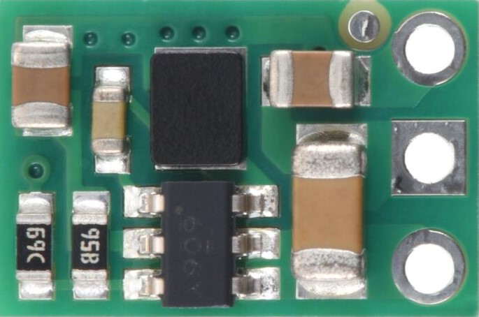
The Pololu 5V, 500mA Step-Down Voltage Regulator D45V5F5 is a compact and efficient DC-DC buck converter designed to step down a higher input voltage to a stable 5V output. It is capable of supplying up to 500mA of current, making it ideal for powering low-voltage devices such as microcontrollers, sensors, and small electronic modules. Its small size and high efficiency make it a popular choice for portable and embedded applications.
Explore Projects Built with 5V, 500mA Step-Down Voltage Regulator D45V5F5


Explore Projects Built with 5V, 500mA Step-Down Voltage Regulator D45V5F5
Common Applications
- Powering 5V microcontrollers (e.g., Arduino, Raspberry Pi Pico)
- Supplying power to sensors, displays, and communication modules
- Battery-powered projects requiring efficient voltage regulation
- Replacing linear voltage regulators for improved efficiency and reduced heat
Technical Specifications
Key Technical Details
| Parameter | Value |
|---|---|
| Input Voltage Range | 6V to 45V |
| Output Voltage | 5V (regulated) |
| Maximum Output Current | 500mA |
| Efficiency | Up to 90% (depending on input voltage) |
| Quiescent Current | ~200µA |
| Operating Temperature | -40°C to +85°C |
| Dimensions | 0.5" × 0.4" × 0.1" (13mm × 10mm × 3mm) |
| Weight | 0.5g |
Pin Configuration and Descriptions
The D45V5F5 regulator has three pins for easy integration into circuits:
| Pin Name | Description |
|---|---|
| VIN | Input voltage (6V to 45V) |
| GND | Ground (0V reference) |
| VOUT | Regulated 5V output |
Usage Instructions
How to Use the Component in a Circuit
Connect the Input Voltage (VIN):
- Attach the positive terminal of your power source (6V to 45V) to the
VINpin. - Ensure the input voltage is within the specified range to avoid damaging the regulator.
- Attach the positive terminal of your power source (6V to 45V) to the
Connect the Ground (GND):
- Connect the ground of your power source and the ground of your load to the
GNDpin.
- Connect the ground of your power source and the ground of your load to the
Connect the Output Voltage (VOUT):
- Connect the
VOUTpin to the positive terminal of your load. The regulator will provide a stable 5V output.
- Connect the
Add Capacitors (Optional but Recommended):
- For improved stability, place a 10µF capacitor across the
VINandGNDpins. - Similarly, place a 10µF capacitor across the
VOUTandGNDpins.
- For improved stability, place a 10µF capacitor across the
Verify Connections:
- Double-check all connections before powering the circuit to prevent damage.
Important Considerations and Best Practices
- Input Voltage Range: Ensure the input voltage is always between 6V and 45V. Exceeding this range can permanently damage the regulator.
- Heat Dissipation: While the regulator is efficient, it may still generate heat under high loads. Ensure adequate ventilation or heat sinking if necessary.
- Load Current: Do not exceed the maximum output current of 500mA to avoid overloading the regulator.
- Polarity Protection: The regulator does not have built-in reverse polarity protection. Double-check the polarity of your connections.
Example: Using with an Arduino UNO
The D45V5F5 can be used to power an Arduino UNO from a 12V battery. Below is an example circuit and Arduino code to blink an LED.
Circuit Connections
- Connect the 12V battery's positive terminal to the
VINpin of the regulator. - Connect the battery's ground to the
GNDpin of the regulator. - Connect the
VOUTpin of the regulator to the Arduino UNO's5Vpin. - Connect the regulator's
GNDpin to the Arduino UNO'sGNDpin.
Arduino Code
// Blink an LED connected to pin 13 of the Arduino UNO
// Ensure the regulator provides a stable 5V to the Arduino

void setup() {
  pinMode(13, OUTPUT); // Set pin 13 as an output
}

void loop() {
  digitalWrite(13, HIGH); // Turn the LED on
  delay(1000);            // Wait for 1 second
  digitalWrite(13, LOW);  // Turn the LED off
  delay(1000);            // Wait for 1 second
}
Troubleshooting and FAQs
Common Issues and Solutions
No Output Voltage:
- Cause: Input voltage is below 6V or connections are incorrect.
- Solution: Verify that the input voltage is within the 6V to 45V range and check all connections.
Overheating:
- Cause: Excessive load current or insufficient ventilation.
- Solution: Ensure the load current does not exceed 500mA. Improve ventilation or add a heat sink.
Output Voltage Fluctuations:
- Cause: Insufficient input/output capacitors or unstable input voltage.
- Solution: Add 10µF capacitors across
VIN-GNDandVOUT-GND.
Regulator Not Working After Reverse Polarity:
- Cause: The regulator was damaged due to reverse polarity.
- Solution: Replace the regulator and use a diode for polarity protection.
FAQs
Q: Can I use this regulator to power a Raspberry Pi?
A: No, the D45V5F5 is not suitable for powering a Raspberry Pi, as it requires more than 500mA of current under load.
Q: What happens if I exceed the maximum input voltage?
A: Exceeding 45V can permanently damage the regulator. Always ensure the input voltage stays within the specified range.
Q: Can I use this regulator with a 5V input?
A: No, the input voltage must be at least 6V for proper operation. For a 5V input, consider a low dropout regulator instead.
Q: Is the regulator protected against short circuits?
A: Yes, the D45V5F5 has built-in short-circuit protection, but it is still recommended to avoid prolonged short circuits.
This concludes the documentation for the Pololu 5V, 500mA Step-Down Voltage Regulator D45V5F5.