
How to Use MaixCAM2: Examples, Pinouts, and Specs
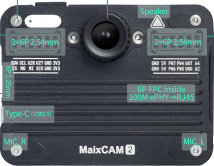
 Design with MaixCAM2 in Cirkit Designer
Introduction
The MaixCAM2, manufactured by Sipeed, is a compact and powerful camera module designed for AI and machine learning applications. It features a high-resolution image sensor and integrated processing capabilities, making it ideal for tasks such as object detection, facial recognition, and image classification. The module is widely used in robotics, IoT projects, and other embedded systems requiring on-device AI processing.
Explore Projects Built with MaixCAM2
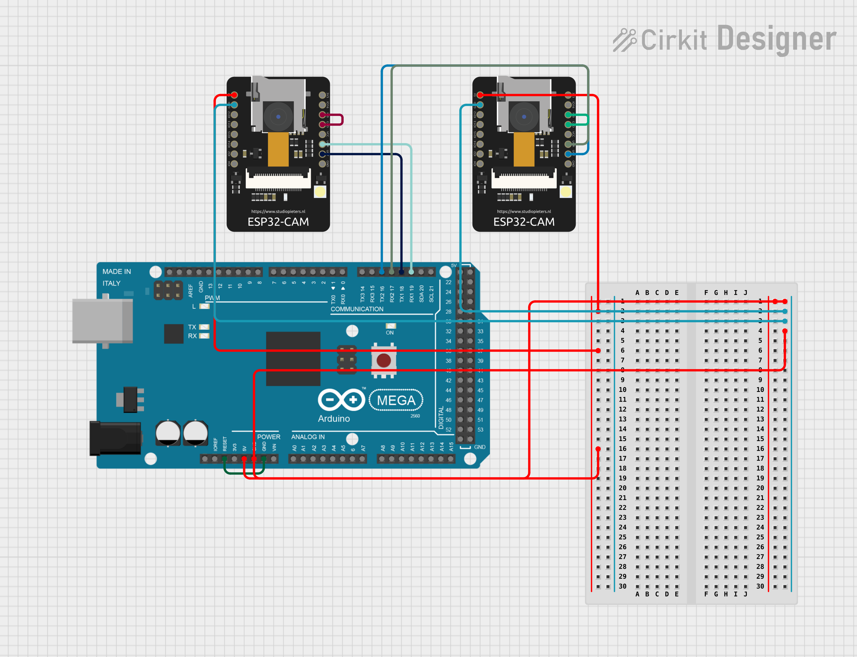 Open Project in Cirkit Designer
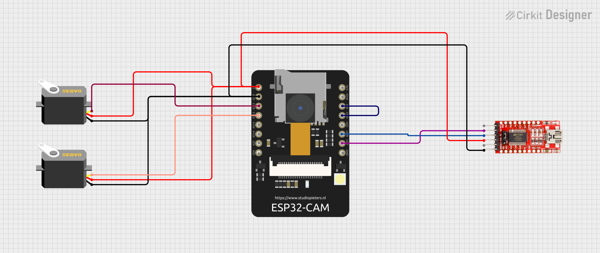 Open Project in Cirkit Designer
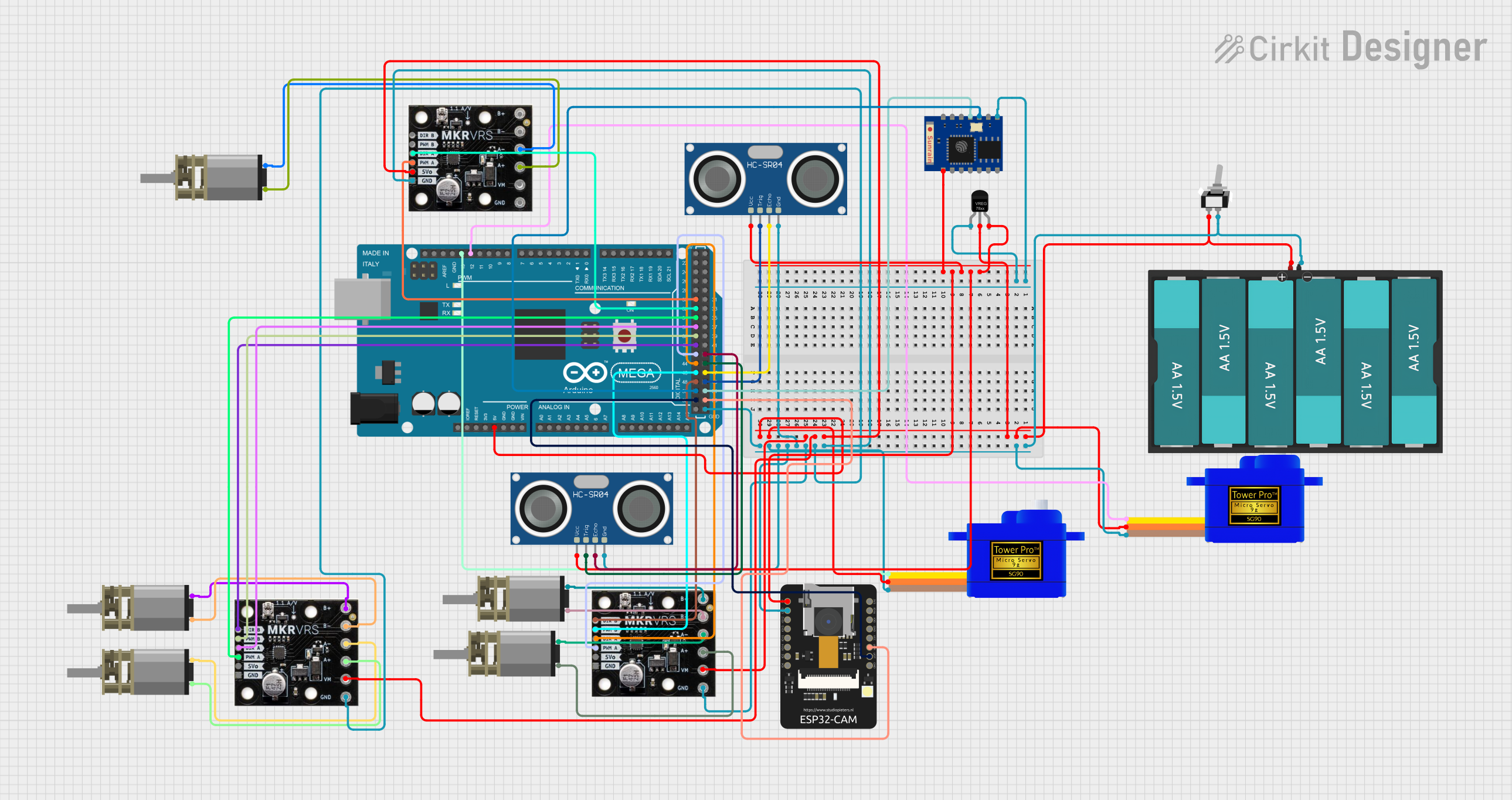 Open Project in Cirkit Designer
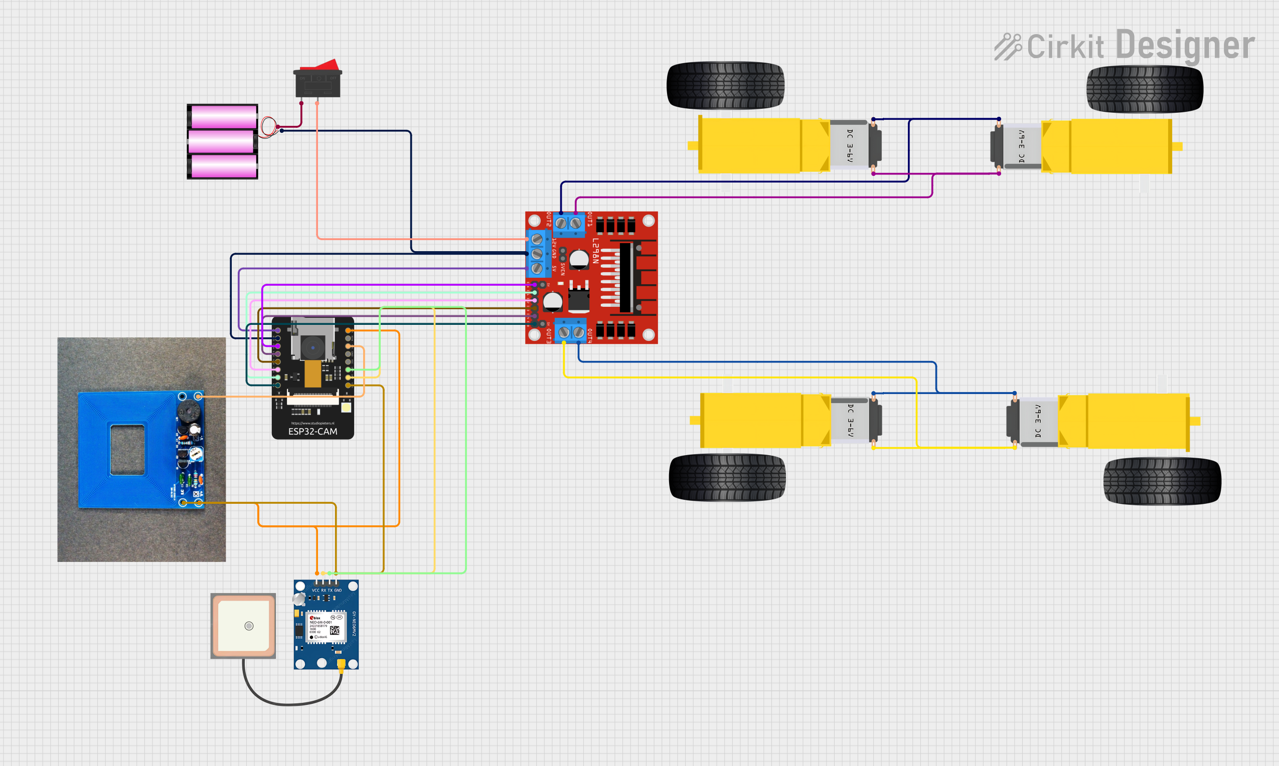 Open Project in Cirkit Designer
Explore Projects Built with MaixCAM2
Open Project in Cirkit DesignerOpen Project in Cirkit DesignerOpen Project in Cirkit DesignerOpen Project in Cirkit DesignerCommon Applications
- Robotics: Object tracking and navigation
- IoT: Smart home devices and surveillance systems
- AI Education: Learning and prototyping machine learning models
- Industrial Automation: Quality control and defect detection
- Wearable Devices: Gesture recognition and activity monitoring
Technical Specifications
The MaixCAM2 is built to deliver high performance in a small form factor. Below are its key technical details:
General Specifications
| Parameter | Value |
|---|---|
| Processor | Kendryte K210 (dual-core RISC-V 64-bit) |
| Image Sensor | OV2640 (2MP, 1600x1200 resolution) |
| AI Acceleration | Built-in KPU (Neural Network Processor) |
| RAM | 8 MB SRAM |
| Flash Storage | 16 MB NOR Flash |
| Communication Interfaces | UART, SPI, I2C, GPIO |
| Power Supply Voltage | 5V (via USB or external power source) |
| Dimensions | 30mm x 30mm |
Pin Configuration
The MaixCAM2 features a 24-pin header for interfacing with external devices. Below is the pinout and description:
| Pin Number | Pin Name | Description |
|---|---|---|
| 1 | VCC | Power input (5V) |
| 2 | GND | Ground |
| 3 | TX | UART Transmit |
| 4 | RX | UART Receive |
| 5 | SCL | I2C Clock |
| 6 | SDA | I2C Data |
| 7 | SPI_CS | SPI Chip Select |
| 8 | SPI_CLK | SPI Clock |
| 9 | SPI_MOSI | SPI Master Out Slave In |
| 10 | SPI_MISO | SPI Master In Slave Out |
| 11-14 | GPIO0-3 | General Purpose Input/Output |
| 15 | RESET | Reset Pin |
| 16 | BOOT | Boot Mode Selection |
| 17-24 | NC | Not Connected |
Usage Instructions
The MaixCAM2 is designed to be user-friendly and can be integrated into various projects with minimal setup. Below are the steps to use the module effectively:
Connecting the MaixCAM2
- Power Supply: Connect the VCC and GND pins to a 5V power source.
- Communication Interface: Use UART, SPI, or I2C to communicate with the module, depending on your application.
- Peripheral Connections: Attach additional sensors or actuators to the GPIO pins as needed.
Using MaixCAM2 with Arduino UNO
Although the MaixCAM2 is typically used with more advanced microcontrollers, it can be interfaced with an Arduino UNO for basic tasks. Below is an example of interfacing the MaixCAM2 via UART:
Arduino Code Example
#include <SoftwareSerial.h>

// Define RX and TX pins for SoftwareSerial
SoftwareSerial mySerial(10, 11); // RX = Pin 10, TX = Pin 11

void setup() {
  // Initialize Serial Monitor
  Serial.begin(9600);
  while (!Serial) {
    ; // Wait for Serial Monitor to open
  }
  Serial.println("MaixCAM2 UART Test");

  // Initialize SoftwareSerial for MaixCAM2
  mySerial.begin(115200); // Default baud rate for MaixCAM2
}

void loop() {
  // Send a test command to MaixCAM2
  mySerial.println("AT"); // Example command to check communication
  delay(100);

  // Read response from MaixCAM2
  if (mySerial.available()) {
    String response = mySerial.readString();
    Serial.println("Response from MaixCAM2: " + response);
  }
}
Important Considerations
- Power Requirements: Ensure a stable 5V power supply to avoid performance issues.
- Baud Rate: The default UART baud rate is 115200. Configure your microcontroller accordingly.
- Firmware Updates: Check for firmware updates from Sipeed to access the latest features and bug fixes.
- Heat Management: The module may heat up during intensive AI tasks. Consider adding a heatsink if necessary.
Troubleshooting and FAQs
Common Issues and Solutions
No Response from MaixCAM2
- Cause: Incorrect wiring or baud rate mismatch.
- Solution: Double-check the connections and ensure the UART baud rate is set to 115200.
Image Quality is Poor
- Cause: Low lighting conditions or incorrect focus.
- Solution: Improve lighting or adjust the focus of the OV2640 sensor.
Module Overheating
- Cause: Prolonged AI processing without proper ventilation.
- Solution: Add a heatsink or improve airflow around the module.
Firmware Update Fails
- Cause: Power interruption or incorrect firmware file.
- Solution: Ensure a stable power supply and verify the firmware file before updating.
FAQs
Q: Can the MaixCAM2 run custom AI models?
A: Yes, the MaixCAM2 supports custom AI models trained using tools like TensorFlow or Keras. Models must be converted to a format compatible with the KPU.
Q: Is the MaixCAM2 compatible with Raspberry Pi?
A: Yes, the MaixCAM2 can be interfaced with Raspberry Pi via UART, SPI, or I2C.
Q: What is the maximum frame rate of the camera?
A: The OV2640 sensor supports up to 30 FPS at VGA resolution (640x480).
Q: Can I use the MaixCAM2 for audio processing?
A: While the MaixCAM2 is primarily designed for image processing, the K210 processor supports basic audio processing tasks.
By following this documentation, users can effectively integrate the MaixCAM2 into their projects and troubleshoot common issues.