
How to Use ST3215 Servo: Examples, Pinouts, and Specs
 Design with ST3215 Servo in Cirkit Designer
Introduction
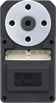
The ST3215 Servo, manufactured by Waveshare, is a high-performance servo motor designed for precise angular position control. It is widely used in robotics, automation systems, RC vehicles, and other applications requiring accurate and reliable motion control. The servo operates using Pulse Width Modulation (PWM) signals and includes a feedback mechanism to ensure precise positioning.
Explore Projects Built with ST3215 Servo
 Open Project in Cirkit Designer
 Open Project in Cirkit Designer
 Open Project in Cirkit Designer
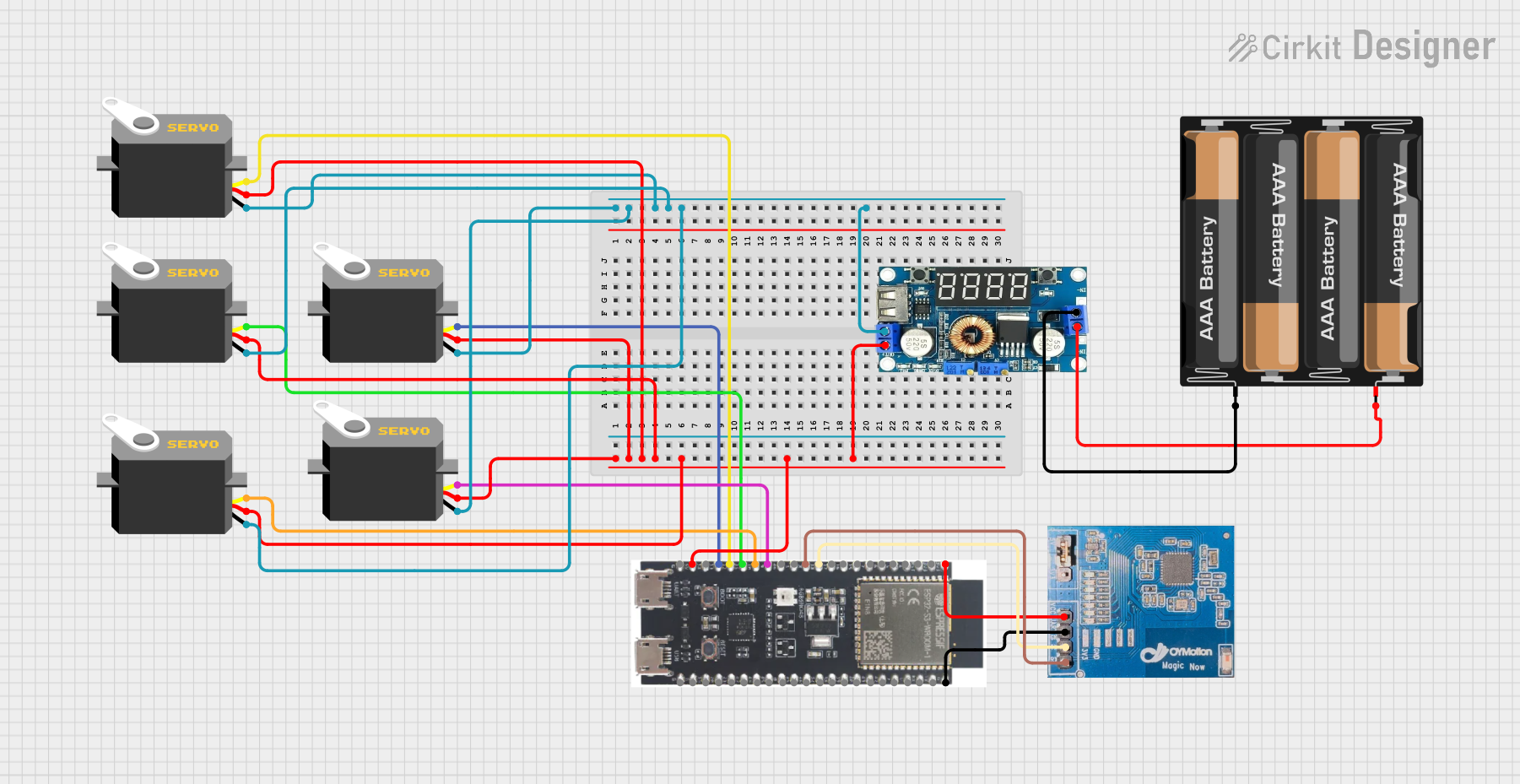 Open Project in Cirkit Designer
Explore Projects Built with ST3215 Servo
Open Project in Cirkit DesignerOpen Project in Cirkit DesignerOpen Project in Cirkit DesignerOpen Project in Cirkit DesignerCommon Applications
- Robotic arms and grippers
- RC cars, boats, and planes
- Automated machinery
- Pan-tilt camera systems
- Educational and DIY electronics projects
Technical Specifications
The following table outlines the key technical details of the ST3215 Servo:
| Parameter | Specification |
|---|---|
| Operating Voltage | 4.8V to 6.0V |
| Stall Torque | 3.2 kg·cm (at 4.8V), 3.5 kg·cm (at 6.0V) |
| Operating Speed | 0.15 sec/60° (at 4.8V), 0.12 sec/60° (at 6.0V) |
| Control Signal | PWM (Pulse Width Modulation) |
| PWM Pulse Range | 500 µs to 2500 µs |
| Angle Range | 0° to 180° |
| Connector Type | 3-pin female header (GND, VCC, PWM) |
| Dimensions | 32 mm x 15 mm x 30 mm |
| Weight | 25 g |
Pin Configuration
The ST3215 Servo has a 3-pin connector. The pinout is as follows:
| Pin Number | Name | Description |
|---|---|---|
| 1 | GND | Ground connection |
| 2 | VCC | Power supply (4.8V to 6.0V) |
| 3 | PWM | PWM signal input for position control |
Usage Instructions
Connecting the ST3215 Servo
- Power Supply: Connect the VCC pin to a 5V or 6V power source and the GND pin to the ground of your circuit. Ensure the power supply can provide sufficient current (at least 1A) to avoid voltage drops.
- PWM Signal: Connect the PWM pin to a microcontroller or servo driver capable of generating PWM signals. For example, an Arduino UNO can be used to control the servo.
Controlling the Servo with Arduino UNO
Below is an example code to control the ST3215 Servo using an Arduino UNO:
#include <Servo.h> // Include the Servo library

Servo myServo; // Create a Servo object to control the ST3215

void setup() {
  myServo.attach(9); // Attach the servo to pin 9 on the Arduino
}

void loop() {
  myServo.write(0); // Move the servo to 0 degrees
  delay(1000); // Wait for 1 second

  myServo.write(90); // Move the servo to 90 degrees
  delay(1000); // Wait for 1 second

  myServo.write(180); // Move the servo to 180 degrees
  delay(1000); // Wait for 1 second
}
Important Considerations
- Power Supply: Use a stable power source to prevent erratic behavior. Avoid powering the servo directly from the Arduino's 5V pin if the servo requires high current.
- PWM Signal: Ensure the PWM signal is within the specified range (500 µs to 2500 µs) to avoid damaging the servo.
- Mechanical Load: Do not exceed the servo's torque rating to prevent overheating or damage.
Troubleshooting and FAQs
Common Issues and Solutions
Servo Not Moving
- Cause: Incorrect wiring or insufficient power supply.
- Solution: Double-check the connections and ensure the power supply meets the voltage and current requirements.
Erratic or Jittery Movement
- Cause: Noise in the PWM signal or unstable power supply.
- Solution: Use a decoupling capacitor near the servo's power pins and ensure the PWM signal is clean.
Servo Overheating
- Cause: Excessive mechanical load or prolonged operation at stall torque.
- Solution: Reduce the load on the servo and avoid operating it at stall torque for extended periods.
Limited Range of Motion
- Cause: PWM signal out of range or mechanical obstruction.
- Solution: Verify the PWM signal is within the 500 µs to 2500 µs range and check for physical obstructions.
FAQs
Q: Can I control multiple ST3215 Servos with one Arduino?
A: Yes, you can control multiple servos using different PWM-capable pins on the Arduino. Use the Servo library to manage multiple servo objects.
Q: What happens if I exceed the servo's torque rating?
A: Exceeding the torque rating can cause the servo to overheat, stall, or become damaged. Always operate within the specified limits.
Q: Can I power the servo directly from the Arduino?
A: It is not recommended to power the servo directly from the Arduino's 5V pin, as the servo may draw more current than the Arduino can supply. Use an external power source instead.
Q: How do I extend the servo's lifespan?
A: Avoid overloading the servo, ensure proper cooling, and use a stable power supply to extend its lifespan.