Cirkit Designer Logo
Cirkit Designer
Your all-in-one circuit design IDE
Home / 
Component Documentation

How to Use rtc: Examples, Pinouts, and Specs

Image of rtc
Cirkit Designer LogoDesign with rtc in Cirkit Designer

Introduction

A Real-Time Clock (RTC) is a timekeeping device designed to maintain accurate time and date information, even when the main power supply is disconnected. This is achieved through the use of a small backup battery. RTCs are essential in applications where precise timekeeping is required, such as data logging, scheduling, and time-stamping events.

The Arduino UNO, when paired with an RTC module, can be used to create projects that require accurate timekeeping, such as alarm clocks, timers, or systems that log data with timestamps.

Explore Projects Built with rtc

Use Cirkit Designer to design, explore, and prototype these projects online. Some projects support real-time simulation. Click "Open Project" to start designing instantly!
Arduino UNO and Sim800l Battery-Powered Real-Time Clock with GSM Communication
Image of circuit1: A project utilizing rtc in a practical application
This circuit integrates an Arduino UNO with a DS3231 RTC module for real-time clock functionality and a Sim800l GSM module for communication. The Arduino is powered by a Li-ion battery and interfaces with the RTC via I2C, while the GSM module is connected for serial communication and powered through a resistor network.
Cirkit Designer LogoOpen Project in Cirkit Designer
Arduino UNO-Based Smart Home Automation System with Bluetooth and RTC
Image of Pill Dispenser: A project utilizing rtc in a practical application
This circuit is a microcontroller-based system using an Arduino UNO to control various components including an RTC module, Bluetooth module, LCD display, pushbutton, buzzer, and multiple DC motors via motor drivers. The system is powered by a 5V adapter and is designed for real-time monitoring and control, with communication capabilities through Bluetooth and visual feedback via the LCD.
Cirkit Designer LogoOpen Project in Cirkit Designer
Arduino Nano Based Real-Time Clock Display with TM1637
Image of 7segmant: A project utilizing rtc in a practical application
This circuit features an Arduino Nano interfacing with a DS3231 Real-Time Clock for timekeeping and a TM1637 display module for visual output. The Arduino facilitates I2C communication with the RTC and controls the display using digital IO, serving as the central processing unit for a digital clock or timer application.
Cirkit Designer LogoOpen Project in Cirkit Designer
Arduino UNO with DS1307 RTC Controlled LED Lighting System
Image of li8: A project utilizing rtc in a practical application
This circuit features an Arduino UNO connected to a DS1307 Real Time Clock (RTC) module for timekeeping and a red LED with a series resistor for indication purposes. The Arduino communicates with the RTC via I2C (using A4 and A5 pins for SDA and SCL, respectively), and controls the LED connected to digital pin D8 through a 330-ohm resistor. The embedded code sets the RTC time, checks the current time, and turns the LED on or off based on the specified time condition (between 11:00 AM and 11:43 AM).
Cirkit Designer LogoOpen Project in Cirkit Designer

Explore Projects Built with rtc

Use Cirkit Designer to design, explore, and prototype these projects online. Some projects support real-time simulation. Click "Open Project" to start designing instantly!
Image of circuit1: A project utilizing rtc in a practical application
Arduino UNO and Sim800l Battery-Powered Real-Time Clock with GSM Communication
This circuit integrates an Arduino UNO with a DS3231 RTC module for real-time clock functionality and a Sim800l GSM module for communication. The Arduino is powered by a Li-ion battery and interfaces with the RTC via I2C, while the GSM module is connected for serial communication and powered through a resistor network.
Cirkit Designer LogoOpen Project in Cirkit Designer
Image of Pill Dispenser: A project utilizing rtc in a practical application
Arduino UNO-Based Smart Home Automation System with Bluetooth and RTC
This circuit is a microcontroller-based system using an Arduino UNO to control various components including an RTC module, Bluetooth module, LCD display, pushbutton, buzzer, and multiple DC motors via motor drivers. The system is powered by a 5V adapter and is designed for real-time monitoring and control, with communication capabilities through Bluetooth and visual feedback via the LCD.
Cirkit Designer LogoOpen Project in Cirkit Designer
Image of 7segmant: A project utilizing rtc in a practical application
Arduino Nano Based Real-Time Clock Display with TM1637
This circuit features an Arduino Nano interfacing with a DS3231 Real-Time Clock for timekeeping and a TM1637 display module for visual output. The Arduino facilitates I2C communication with the RTC and controls the display using digital IO, serving as the central processing unit for a digital clock or timer application.
Cirkit Designer LogoOpen Project in Cirkit Designer
Image of li8: A project utilizing rtc in a practical application
Arduino UNO with DS1307 RTC Controlled LED Lighting System
This circuit features an Arduino UNO connected to a DS1307 Real Time Clock (RTC) module for timekeeping and a red LED with a series resistor for indication purposes. The Arduino communicates with the RTC via I2C (using A4 and A5 pins for SDA and SCL, respectively), and controls the LED connected to digital pin D8 through a 330-ohm resistor. The embedded code sets the RTC time, checks the current time, and turns the LED on or off based on the specified time condition (between 11:00 AM and 11:43 AM).
Cirkit Designer LogoOpen Project in Cirkit Designer

Technical Specifications

Below are the general technical specifications for an RTC module compatible with the Arduino UNO:

  • Manufacturer: Arduino
  • Part ID: UNO
  • Operating Voltage: 3.3V to 5V
  • Backup Battery: CR2032 or similar coin cell battery
  • Communication Protocol: I2C (Inter-Integrated Circuit)
  • Typical Accuracy: ±2 ppm to ±20 ppm (depending on the specific RTC chip)
  • Temperature Range: -40°C to +85°C (varies by model)

Pin Configuration and Descriptions

The RTC module typically has the following pins:

Pin Name Description
VCC Power supply pin (3.3V or 5V, depending on the module).
GND Ground pin.
SDA Serial Data Line for I2C communication.
SCL Serial Clock Line for I2C communication.
BAT Backup battery pin (optional, for connecting a CR2032 battery).
SQW/OUT Square Wave Output pin (optional, used for generating a clock signal).

Usage Instructions

How to Use the RTC in a Circuit

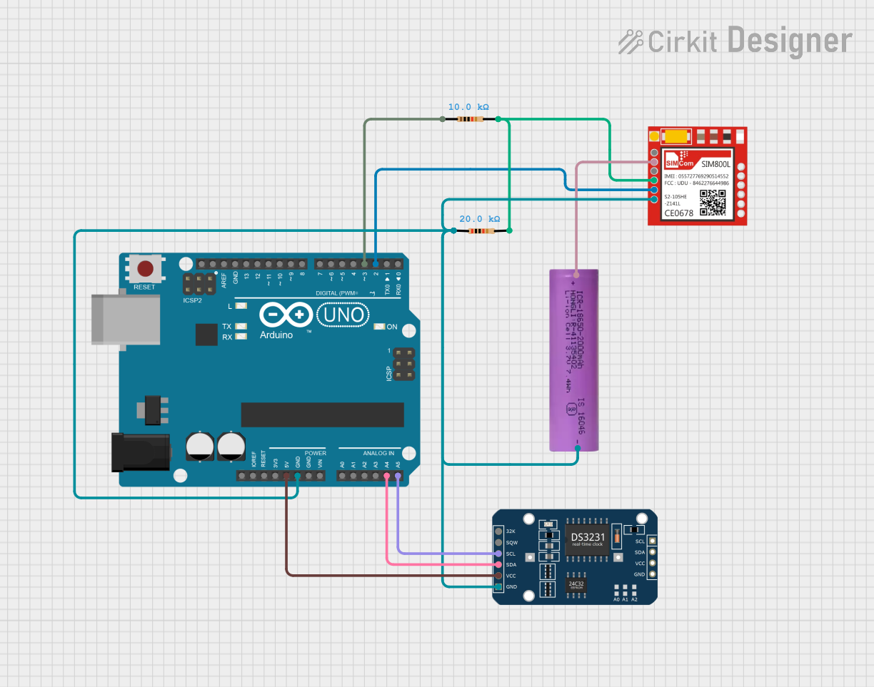
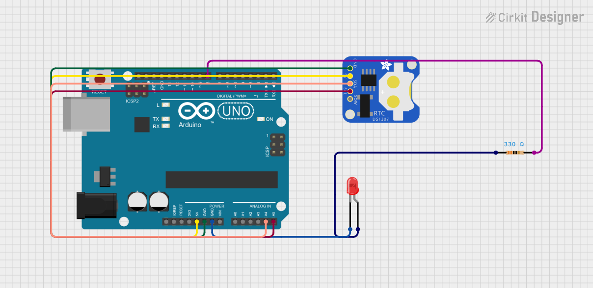
  1. Connect the RTC Module to the Arduino UNO:

    • Connect the VCC pin of the RTC module to the 5V pin on the Arduino UNO.
    • Connect the GND pin of the RTC module to the GND pin on the Arduino UNO.
    • Connect the SDA pin of the RTC module to the A4 pin on the Arduino UNO.
    • Connect the SCL pin of the RTC module to the A5 pin on the Arduino UNO.
  2. Install the Required Library:

    • Use the Arduino IDE to install the RTClib library, which provides functions for interfacing with RTC modules.
    • To install the library, go to Sketch > Include Library > Manage Libraries, search for RTClib, and click Install.
  3. Upload Example Code:

    • Use the following example code to set the time and read the current time from the RTC module.
#include <Wire.h>
#include <RTClib.h>

// Create an RTC object
RTC_DS1307 rtc;

void setup() {
  Serial.begin(9600); // Initialize serial communication at 9600 baud
  if (!rtc.begin()) {
    Serial.println("Couldn't find RTC");
    while (1); // Halt the program if the RTC is not found
  }

  if (!rtc.isrunning()) {
    Serial.println("RTC is NOT running, setting the time...");
    // Set the RTC to the date & time this sketch was compiled
    rtc.adjust(DateTime(F(__DATE__), F(__TIME__)));
  }
}

void loop() {
  DateTime now = rtc.now(); // Get the current date and time

  // Print the current date and time to the Serial Monitor
  Serial.print(now.year(), DEC);
  Serial.print('/');
  Serial.print(now.month(), DEC);
  Serial.print('/');
  Serial.print(now.day(), DEC);
  Serial.print(" ");
  Serial.print(now.hour(), DEC);
  Serial.print(':');
  Serial.print(now.minute(), DEC);
  Serial.print(':');
  Serial.print(now.second(), DEC);
  Serial.println();

  delay(1000); // Wait for 1 second before updating the time
}

Important Considerations and Best Practices

  • Always ensure the backup battery is installed to maintain timekeeping when the main power is off.
  • Use pull-up resistors on the SDA and SCL lines if they are not already included on the RTC module.
  • Avoid placing the RTC module near high-frequency components to minimize interference.
  • Regularly check and replace the backup battery to ensure uninterrupted operation.

Troubleshooting and FAQs

Common Issues and Solutions

  1. RTC Not Detected:

    • Ensure the SDA and SCL pins are correctly connected to the Arduino UNO.
    • Verify that the RTClib library is installed and included in your sketch.
    • Check the power supply to the RTC module.
  2. Incorrect Time Displayed:

    • Ensure the RTC is initialized and the time is set correctly using the rtc.adjust() function.
    • Verify that the backup battery is installed and functional.
  3. Time Resets After Power Loss:

    • Check the backup battery connection and replace the battery if necessary.

FAQs

Q: Can I use the RTC module with other microcontrollers?
A: Yes, the RTC module can be used with other microcontrollers that support I2C communication, such as ESP32, ESP8266, or Raspberry Pi.

Q: How long does the backup battery last?
A: The backup battery can last several years, depending on the RTC module's power consumption and the battery's capacity.

Q: Can I use multiple I2C devices with the RTC module?
A: Yes, I2C supports multiple devices on the same bus. Ensure each device has a unique address.

Q: What happens if the backup battery is removed?
A: The RTC will lose its timekeeping functionality when the main power is off, and the time will need to be reset when power is restored.