How to Use WS2812: Examples, Pinouts, and Specs
Introduction
The WS2812 is a smart RGB LED that integrates a control circuit and RGB chip into a single package. This design allows for precise individual control of each LED's color and brightness, enabling the creation of dynamic lighting effects. The WS2812 is widely used in decorative lighting, LED strips, signage, and displays due to its ease of use and vibrant color output.
Explore Projects Built with WS2812

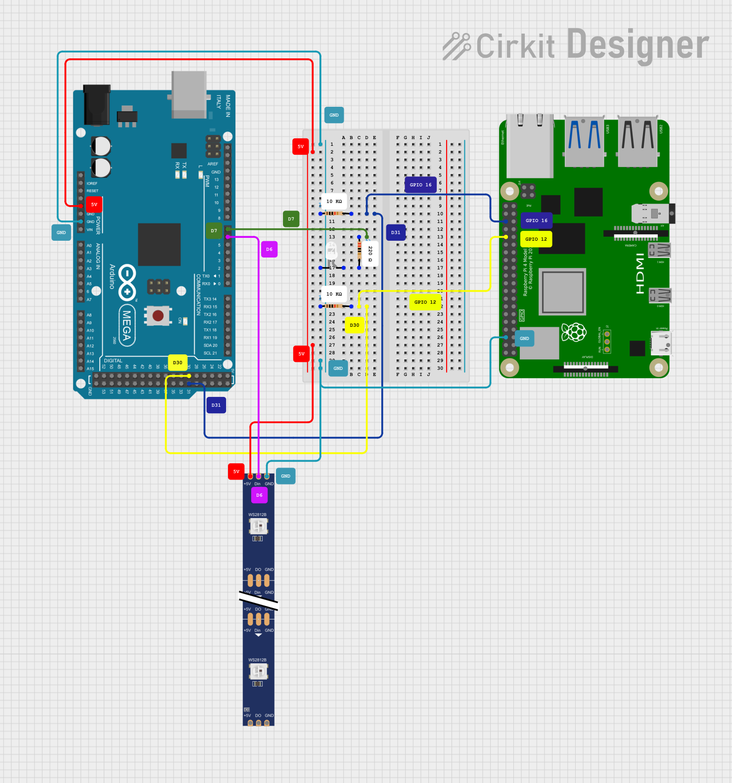

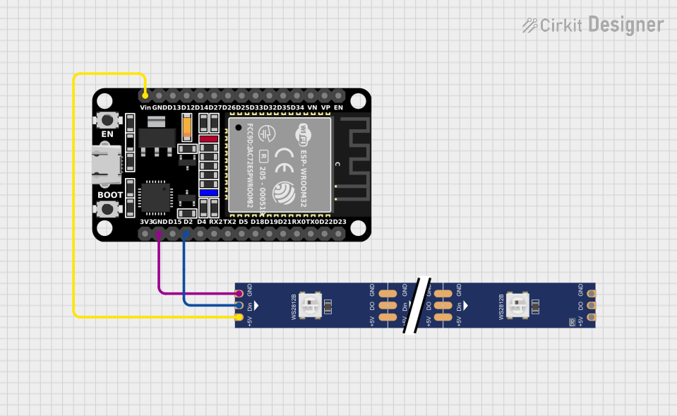
Explore Projects Built with WS2812
Common Applications
- LED strips for home and commercial decorative lighting
- Digital signage and advertising displays
- Wearable electronics and art installations
- Gaming peripherals and PC case lighting
- Holiday decorations and custom light shows
Technical Specifications
The WS2812 operates as a chainable RGB LED, where each LED can be individually addressed using a single data line. Below are the key technical details:
Key Specifications
| Parameter | Value |
|---|---|
| Operating Voltage | 3.5V to 5.3V |
| Operating Current | ~20mA per color channel |
| Maximum Current (RGB) | ~60mA per LED (all channels) |
| Communication Protocol | Single-wire serial |
| Data Transfer Rate | 800 Kbps |
| LED Color Depth | 24-bit (8 bits per channel) |
| Operating Temperature | -25°C to +80°C |
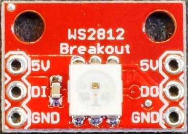
Pin Configuration
The WS2812 typically has four pins. Below is the pinout description:
| Pin Name | Pin Number | Description |
|---|---|---|
| VDD | 1 | Power supply (3.5V to 5.3V) |
| DOUT | 2 | Data output for chaining to the next LED |
| GND | 3 | Ground connection |
| DIN | 4 | Data input for receiving control signals |
Usage Instructions
The WS2812 is controlled using a single-wire communication protocol. Each LED in a chain receives data, processes its portion, and forwards the remaining data to the next LED. Below are the steps to use the WS2812 in a circuit:
Circuit Connection
- Power Supply: Connect the VDD pin to a 5V power source and the GND pin to ground.
- Data Line: Connect the DIN pin to a microcontroller's digital output pin. Use a resistor (330-500 ohms) in series with the data line to protect the LED.
- Capacitor: Place a 100µF capacitor between VDD and GND to stabilize the power supply.
- Chaining LEDs: Connect the DOUT pin of one LED to the DIN pin of the next LED in the chain.
Arduino UNO Example Code
The WS2812 can be easily controlled using the Arduino platform and the Adafruit NeoPixel library. Below is an example code snippet:
#include <Adafruit_NeoPixel.h>

// Define the number of LEDs in the chain
#define NUM_LEDS 8

// Define the pin connected to the WS2812 DIN
#define DATA_PIN 6

// Create a NeoPixel object
Adafruit_NeoPixel strip = Adafruit_NeoPixel(NUM_LEDS, DATA_PIN, NEO_GRB + NEO_KHZ800);

void setup() {
  strip.begin();  // Initialize the NeoPixel library
  strip.show();   // Turn off all LEDs initially
}

void loop() {
  // Set the first LED to red
  strip.setPixelColor(0, strip.Color(255, 0, 0)); // Red color
  // Set the second LED to green
  strip.setPixelColor(1, strip.Color(0, 255, 0)); // Green color
  // Set the third LED to blue
  strip.setPixelColor(2, strip.Color(0, 0, 255)); // Blue color
  // Update the LED strip to display the colors
  strip.show();
  delay(500);  // Wait for 500ms before repeating
}
Best Practices
- Use a level shifter if your microcontroller operates at 3.3V logic to ensure proper data signal levels.
- Avoid powering too many LEDs directly from the microcontroller; use an external power supply for large LED arrays.
- Add a decoupling capacitor (100µF) near the power input to reduce voltage fluctuations.
Troubleshooting and FAQs
Common Issues
LEDs Not Lighting Up
- Cause: Incorrect wiring or insufficient power supply.
- Solution: Double-check the connections, ensure the power supply provides enough current, and verify the data pin is correctly connected.
Flickering LEDs
- Cause: Unstable power supply or noisy data signal.
- Solution: Add a capacitor across the power lines and use a resistor in series with the data line.
Incorrect Colors
- Cause: Data signal timing issues or incorrect library settings.
- Solution: Ensure the correct LED type (e.g., NEO_GRB) is specified in the code and verify the microcontroller's timing.
Only the First LED Works
- Cause: Data signal not passing through to subsequent LEDs.
- Solution: Check the DOUT-to-DIN connection between LEDs and ensure the first LED is functioning properly.
FAQs
Q: Can I control WS2812 LEDs without a library?
A: Yes, but it requires precise timing to generate the 800 Kbps signal. Using a library like Adafruit NeoPixel simplifies the process.
Q: How many LEDs can I chain together?
A: Theoretically, you can chain hundreds of LEDs, but practical limits depend on power supply capacity and signal integrity.
Q: Can I power WS2812 LEDs with a 3.3V power supply?
A: While the WS2812 can operate at 3.5V, it is recommended to use a 5V power supply for optimal performance.
Q: Do I need a resistor on the data line?
A: Yes, a 330-500 ohm resistor helps protect the LEDs from voltage spikes and improves signal quality.