How to Use 4PDT: Examples, Pinouts, and Specs
Introduction
The 4PDT (4 Pole Double Throw) switch, manufactured by Comax (Part ID: SK-42F05G6), is a versatile electromechanical device designed to control multiple circuits simultaneously. It features four independent poles, each capable of switching between two outputs. This makes it ideal for applications requiring complex circuit configurations or the control of multiple devices with a single switch.
Explore Projects Built with 4PDT
Explore Projects Built with 4PDT
Common Applications and Use Cases
- Audio signal routing (e.g., switching between audio sources or outputs)
- Industrial control systems
- Robotics and automation
- Model railroads for track switching
- Test equipment and circuit prototyping
Technical Specifications
The following table outlines the key technical details of the Comax SK-42F05G6 4PDT switch:
| Parameter | Value |
|---|---|
| Manufacturer | Comax |
| Part ID | SK-42F05G6 |
| Switch Type | 4 Pole Double Throw (4PDT) |
| Contact Configuration | 4PDT (4 poles, 2 throws per pole) |
| Contact Rating | 5A at 250VAC / 30VDC |
| Insulation Resistance | ≥ 100MΩ at 500VDC |
| Dielectric Strength | 1500VAC for 1 minute |
| Operating Temperature | -25°C to +85°C |
| Mechanical Life | 50,000 operations |
| Mounting Style | Panel mount |
Pin Configuration and Descriptions
The 4PDT switch has 12 terminals, arranged in a 4x3 grid. Each pole has a common terminal (COM), a normally closed (NC) terminal, and a normally open (NO) terminal. The table below describes the pin configuration:
| Pin Number | Description |
|---|---|
| 1 | Pole 1 - Common (COM) |
| 2 | Pole 1 - Normally Closed (NC) |
| 3 | Pole 1 - Normally Open (NO) |
| 4 | Pole 2 - Common (COM) |
| 5 | Pole 2 - Normally Closed (NC) |
| 6 | Pole 2 - Normally Open (NO) |
| 7 | Pole 3 - Common (COM) |
| 8 | Pole 3 - Normally Closed (NC) |
| 9 | Pole 3 - Normally Open (NO) |
| 10 | Pole 4 - Common (COM) |
| 11 | Pole 4 - Normally Closed (NC) |
| 12 | Pole 4 - Normally Open (NO) |
Usage Instructions
How to Use the 4PDT Switch in a Circuit
- Identify the Terminals: Refer to the pin configuration table to locate the common (COM), normally closed (NC), and normally open (NO) terminals for each pole.
- Connect the Circuits:
- Connect the input signal or power source to the COM terminal of each pole.
- Connect the desired output circuits to the NC and NO terminals.
- When the switch is in its default position, the COM terminal is connected to the NC terminal. When toggled, the COM terminal connects to the NO terminal.
- Mount the Switch: Secure the switch to a panel or enclosure using the provided mounting hardware.
- Test the Connections: Verify the continuity between terminals using a multimeter to ensure proper wiring.
Important Considerations and Best Practices
- Current and Voltage Ratings: Ensure the connected circuits do not exceed the switch's rated current (5A) and voltage (250VAC or 30VDC).
- Debouncing: If the switch is used in digital circuits, consider implementing debouncing techniques to avoid false triggering.
- Mechanical Life: Avoid excessive force or rapid toggling to maximize the switch's lifespan.
- Safety: Disconnect power before wiring or modifying the switch to prevent electrical shock or damage.
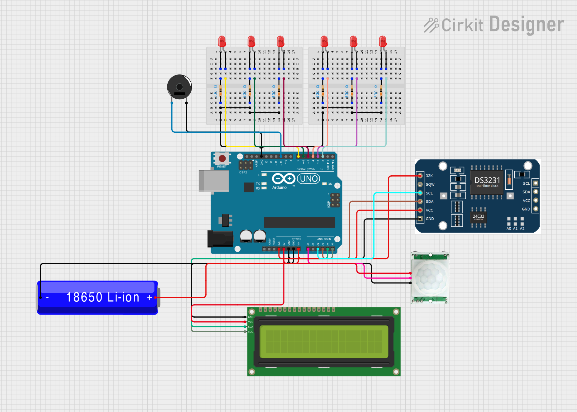
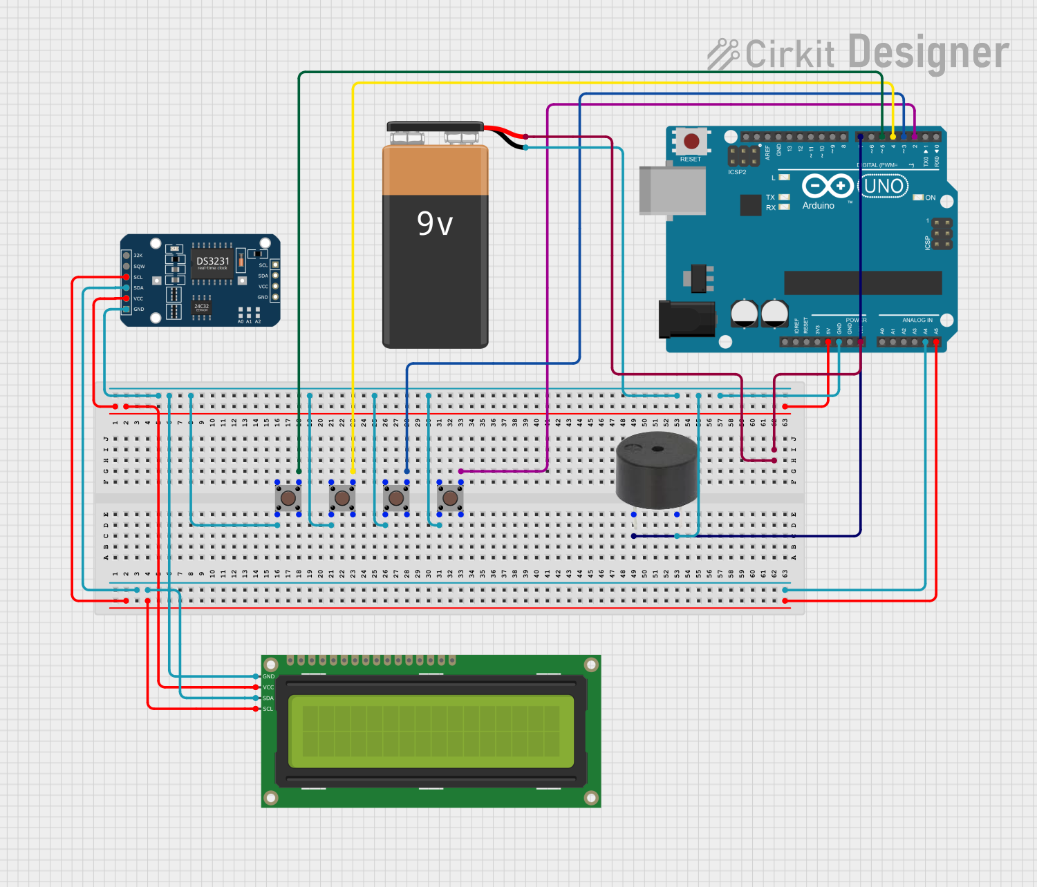
Example: Using the 4PDT Switch with an Arduino UNO
The 4PDT switch can be used to control multiple devices or signals in conjunction with an Arduino. Below is an example of wiring and code to read the state of one pole of the switch:
Wiring
- Connect the COM terminal of one pole to a 5V power source.
- Connect the NC terminal to Arduino digital pin 2.
- Connect the NO terminal to Arduino digital pin 3.
- Use pull-down resistors (10kΩ) on pins 2 and 3 to ensure stable readings.
Code
// Define the pins connected to the switch terminals
const int ncPin = 2; // Normally Closed terminal
const int noPin = 3; // Normally Open terminal

void setup() {
  // Set the pins as inputs
  pinMode(ncPin, INPUT);
  pinMode(noPin, INPUT);

  // Start the serial communication for debugging
  Serial.begin(9600);
}

void loop() {
  // Read the state of the NC and NO terminals
  int ncState = digitalRead(ncPin);
  int noState = digitalRead(noPin);

  // Print the switch state to the serial monitor
  Serial.print("NC State: ");
  Serial.print(ncState); // 1 = connected, 0 = disconnected
  Serial.print(" | NO State: ");
  Serial.println(noState); // 1 = connected, 0 = disconnected

  delay(500); // Wait for 500ms before the next reading
}
Troubleshooting and FAQs
Common Issues and Solutions
Switch Does Not Toggle Properly:
- Cause: Mechanical wear or debris inside the switch.
- Solution: Clean the switch contacts or replace the switch if necessary.
Incorrect Wiring:
- Cause: Misidentification of terminals.
- Solution: Double-check the pin configuration and use a multimeter to verify connections.
Intermittent Connections:
- Cause: Loose or corroded terminals.
- Solution: Ensure all connections are secure and clean the terminals if needed.
Arduino Reads Incorrect States:
- Cause: Floating inputs or lack of pull-down resistors.
- Solution: Add pull-down resistors to stabilize the input signals.
FAQs
Q: Can the 4PDT switch handle DC and AC signals simultaneously?
A: Yes, but ensure the total current and voltage do not exceed the switch's ratings.
Q: How do I debounce the switch in software?
A: Use a delay or a state-change detection algorithm in your code to filter out rapid toggling.
Q: Can I use all four poles independently?
A: Yes, each pole operates independently, allowing for versatile circuit configurations.
Q: Is the switch waterproof?
A: No, the SK-42F05G6 is not waterproof. Use it in dry environments or enclosures.