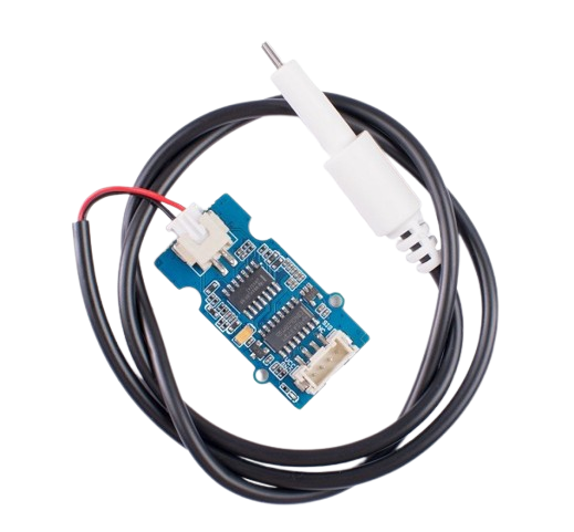
The TDS Meter by VEGA (Part ID: IOT) is a device designed to measure the concentration of dissolved solids in water. It provides an accurate indication of water quality and purity, making it an essential tool for applications such as water filtration systems, aquariums, hydroponics, and environmental monitoring. By measuring the electrical conductivity of water, the TDS meter estimates the total dissolved solids in parts per million (ppm).
Explore Projects Built with TDS
Use Cirkit Designer to design, explore, and prototype these projects online. Some projects support real-time simulation. Click "Open Project" to start designing instantly!
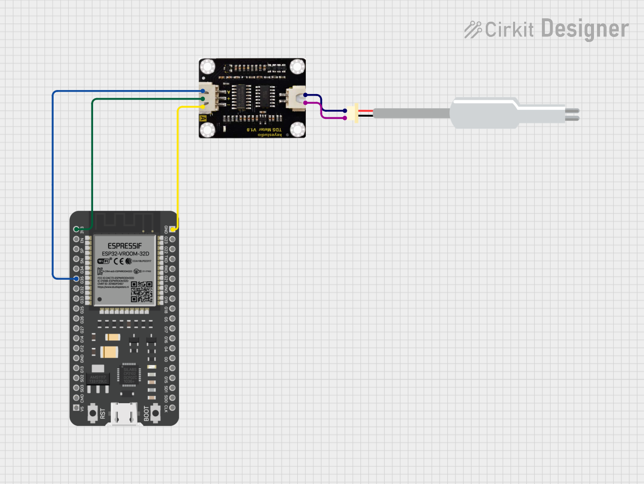
This circuit connects a TDS (Total Dissolved Solids) sensor to an ESP32 microcontroller. The TDS sensor's power is supplied by the ESP32's 3.3V and ground pins, and its analog output is connected to GPIO 35 of the ESP32 for measurement. The purpose of this circuit is to enable the ESP32 to read the TDS level of a solution, which is commonly used in water quality testing.
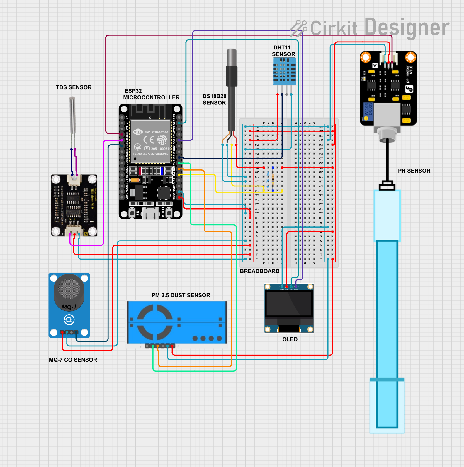
This circuit is an environmental monitoring system using an ESP32 microcontroller to collect data from various sensors, including temperature, humidity, air quality, pH, and TDS sensors. The collected data is displayed on an OLED screen, sent to ThingSpeak for remote monitoring, and email alerts are sent if critical thresholds are exceeded.
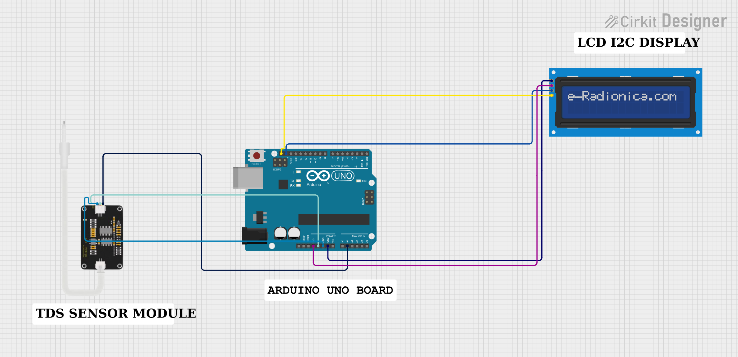
This circuit uses an Arduino UNO to read data from a TDS (Total Dissolved Solids) sensor and display the TDS value and water quality information on a 16x2 I2C LCD screen. The Arduino reads the analog signal from the TDS sensor, converts it to a TDS value, and then displays the value along with a corresponding water quality message on the LCD.
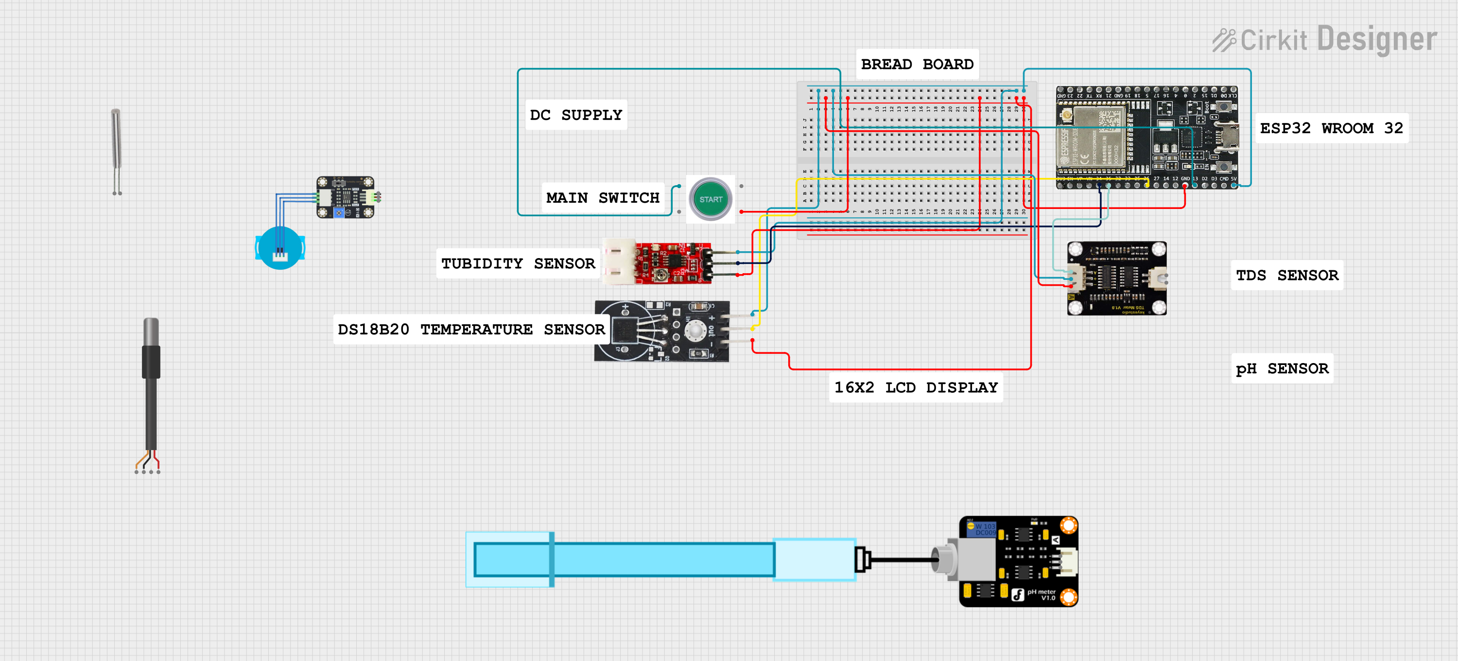
This circuit is a water quality monitoring system that uses an ESP32 microcontroller to measure TDS, pH, temperature, and turbidity of water. The system includes sensors for each parameter and a start switch, with data being displayed on a 16x2 I2C LCD and logged via serial communication.
Water Quality Monitoring: Ensures water is safe for drinking or industrial use.
Aquariums: Maintains optimal water conditions for aquatic life.
Hydroponics: Monitors nutrient levels in water for plant growth.
Environmental Studies: Tracks water pollution and contamination levels.
Industrial Processes: Ensures water purity in manufacturing and chemical processes.
Technical Specifications
The following table outlines the key technical details of the VEGA TDS Meter (IOT):
Parameter
Specification
Operating Voltage
3.3V - 5V DC
Operating Current
< 20mA
Measurement Range
0 - 1000 ppm
Accuracy
±10 ppm
Output Signal
Analog Voltage (0 - 2.3V)
Temperature Range
0°C - 60°C
Dimensions
42mm x 32mm x 8mm
Interface
Analog
Pin Configuration and Descriptions
The TDS meter has a simple 3-pin interface for easy integration into circuits:
Pin
Name
Description
1
VCC
Power supply input (3.3V - 5V DC)
2
GND
Ground connection
3
AOUT
Analog output signal proportional to TDS measurement
Usage Instructions
How to Use the TDS Meter in a Circuit
Power the TDS Meter: Connect the VCC pin to a 3.3V or 5V DC power source and the GND pin to the ground.
Connect the Analog Output: Attach the AOUT pin to an analog input pin of a microcontroller (e.g., Arduino UNO).
Calibrate the Sensor: Use a known TDS solution to calibrate the sensor for accurate readings.
Read the Output: The analog output voltage corresponds to the TDS value in ppm. Use the formula provided in the datasheet or the example code below to convert the voltage to TDS.
Important Considerations and Best Practices
Avoid Immersing the Circuit Board: Only the probe should be submerged in water. Ensure the circuit board remains dry to prevent damage.
Temperature Compensation: For accurate readings, consider the effect of water temperature. Use a temperature sensor for compensation if needed.
Clean the Probe Regularly: Deposits on the probe can affect accuracy. Clean it with distilled water after use.
Avoid High TDS Levels: The sensor is designed for a maximum of 1000 ppm. Exceeding this range may damage the sensor or produce inaccurate results.
Example Code for Arduino UNO
Below is an example of how to use the VEGA TDS Meter with an Arduino UNO:
// Example code for VEGA TDS Meter (IOT) with Arduino UNO
// Reads the analog output and converts it to TDS in ppm

const int TDS_PIN = A0; // Analog pin connected to AOUT of TDS meter
const float VREF = 5.0; // Reference voltage of Arduino UNO (5V)
const float TDS_FACTOR = 0.5; // Conversion factor for TDS calculation

void setup() {
  Serial.begin(9600); // Initialize serial communication
  pinMode(TDS_PIN, INPUT); // Set TDS_PIN as input
}

void loop() {
  int analogValue = analogRead(TDS_PIN); // Read analog value from TDS meter
  float voltage = analogValue * (VREF / 1023.0); // Convert to voltage
  float tdsValue = (voltage / TDS_FACTOR) * 1000; // Convert voltage to TDS (ppm)

  // Print the TDS value to the Serial Monitor
  Serial.print("TDS Value: ");
  Serial.print(tdsValue);
  Serial.println(" ppm");

  delay(1000); // Wait for 1 second before the next reading
}
Troubleshooting and FAQs
Common Issues and Solutions
No Output or Incorrect Readings
Cause: Improper wiring or loose connections.
Solution: Double-check all connections, ensuring VCC, GND, and AOUT are properly connected.
Fluctuating Readings
Cause: Electrical noise or unstable power supply.
Solution: Use a decoupling capacitor (e.g., 0.1µF) between VCC and GND to stabilize the power supply.
Inaccurate TDS Values
Cause: Probe contamination or lack of calibration.
Solution: Clean the probe with distilled water and recalibrate using a known TDS solution.
Sensor Not Responding
Cause: Exceeding the operating range or damaged sensor.
Solution: Ensure the TDS level is within the 0-1000 ppm range. Replace the sensor if damaged.
FAQs
Q1: Can the TDS meter measure salt concentration in seawater?
A1: No, the TDS meter is designed for freshwater applications and cannot accurately measure high salinity levels in seawater.
Q2: How often should I calibrate the TDS meter?
A2: Calibration frequency depends on usage. For critical applications, calibrate weekly. For general use, monthly calibration is sufficient.
Q3: Can I use the TDS meter with a 3.3V microcontroller?
A3: Yes, the TDS meter operates on 3.3V - 5V, making it compatible with 3.3V microcontrollers like ESP32 or 5V boards like Arduino UNO.
Q4: What is the lifespan of the TDS probe?
A4: The probe typically lasts 1-2 years with proper care and maintenance. Regular cleaning and avoiding harsh chemicals can extend its lifespan.

 Open Project in Cirkit Designer