How to Use STM32F103C8T6: Examples, Pinouts, and Specs
Introduction
The STM32F103C8T6 is a 32-bit microcontroller manufactured by STMicroelectronics. It is based on the ARM Cortex-M3 core and is part of the STM32F1 series. This microcontroller is designed for high-performance, low-power embedded applications and offers a rich set of peripherals, making it a versatile choice for a wide range of projects.
Explore Projects Built with STM32F103C8T6

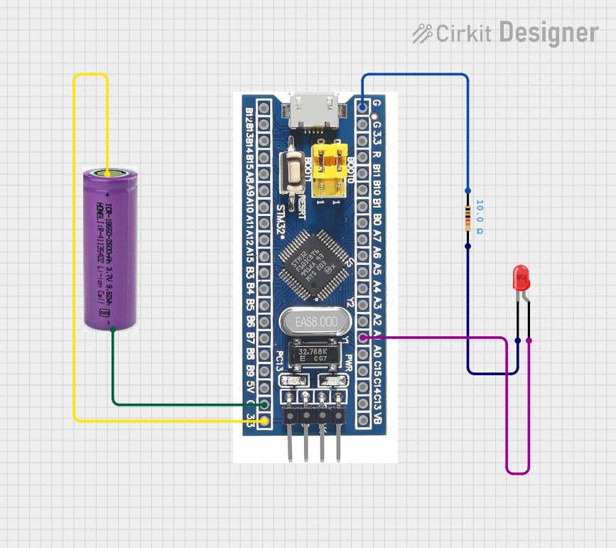

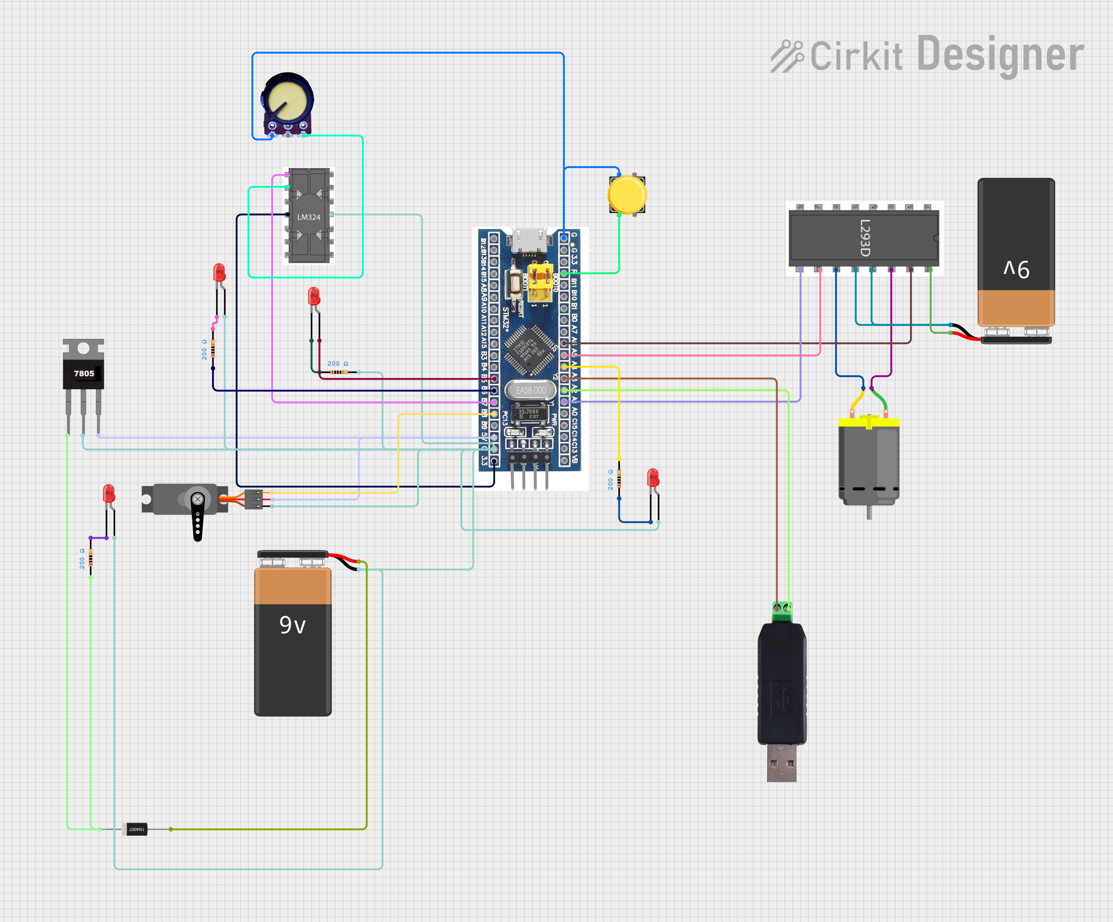
Explore Projects Built with STM32F103C8T6
Common Applications and Use Cases
- Industrial control systems
- Consumer electronics
- IoT devices and smart home applications
- Robotics and automation
- Data acquisition systems
- Motor control and power management
Technical Specifications
The STM32F103C8T6 microcontroller is packed with features that make it suitable for various embedded applications. Below are its key technical specifications:
Key Features
- Core: ARM Cortex-M3, 32-bit RISC
- Operating Frequency: Up to 72 MHz
- Flash Memory: 64 KB
- SRAM: 20 KB
- GPIO Pins: Up to 37 (multiplexed with other functions)
- Communication Interfaces:
- 2x I2C
- 3x USART
- 2x SPI
- 1x CAN
- Timers: 3x 16-bit general-purpose timers, 1x 16-bit advanced timer
- ADC: 12-bit, up to 16 channels
- Operating Voltage: 2.0V to 3.6V
- Power Consumption: Low-power modes available
- Package: LQFP-48 (48-pin)
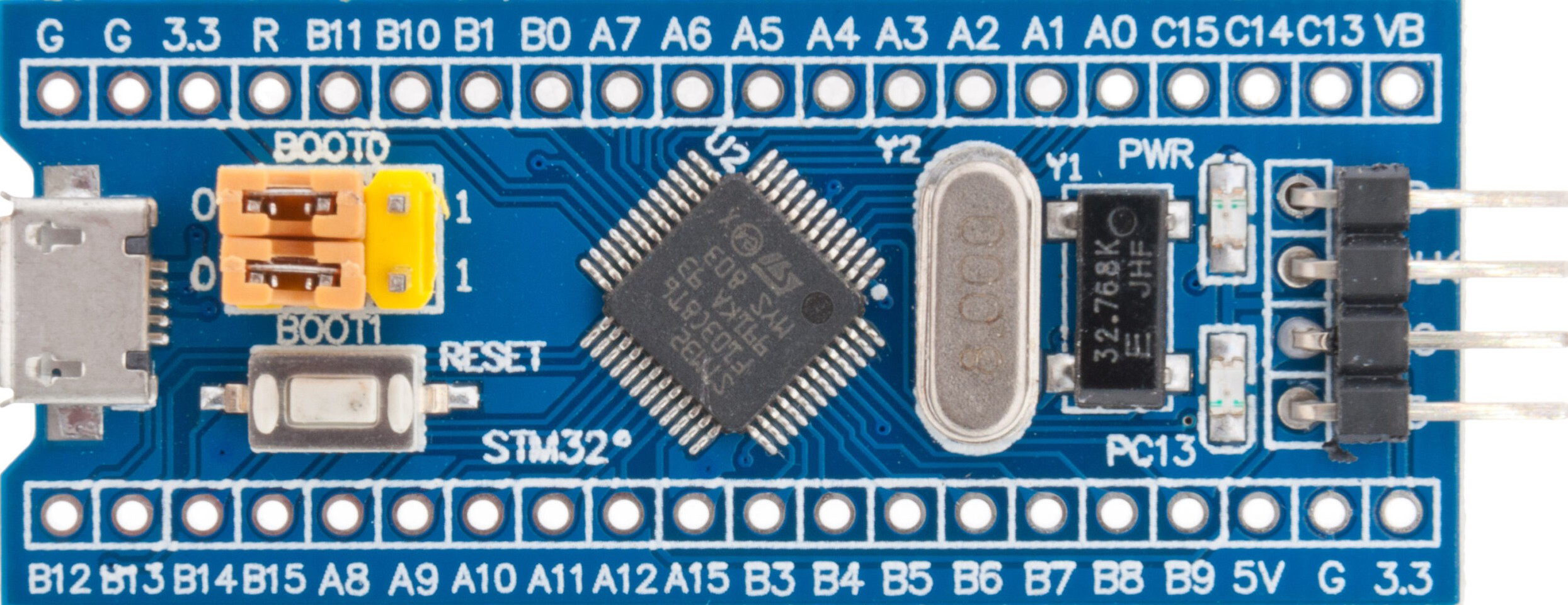
Pin Configuration and Descriptions
The STM32F103C8T6 comes in a 48-pin LQFP package. Below is a table summarizing the pin configuration:
| Pin Number | Pin Name | Function | Description |
|---|---|---|---|
| 1 | VDD | Power Supply | Positive supply voltage (2.0V–3.6V) |
| 2 | VSS | Ground | Ground connection |
| 3 | PA0 | GPIO/ADC_IN0/TIM2_CH1/USART2_CTS | General-purpose I/O or alternate function |
| 4 | PA1 | GPIO/ADC_IN1/TIM2_CH2/USART2_RTS | General-purpose I/O or alternate function |
| 5 | PA2 | GPIO/ADC_IN2/TIM2_CH3/USART2_TX | General-purpose I/O or alternate function |
| ... | ... | ... | ... |
| 48 | NRST | Reset | Active-low reset pin |
Note: For the full pinout and alternate functions, refer to the STM32F103C8T6 datasheet.
Usage Instructions
The STM32F103C8T6 is a versatile microcontroller that can be used in a variety of circuits. Below are the steps and best practices for using this component:
Basic Circuit Setup
- Power Supply: Connect the VDD pin to a 3.3V power source and the VSS pin to ground.
- Reset: Connect the NRST pin to a pull-up resistor (typically 10kΩ) to ensure proper reset functionality.
- Clock Source: Use an external 8 MHz crystal oscillator connected to the OSC_IN and OSC_OUT pins for accurate timing.
- Programming Interface: Use the SWD (Serial Wire Debug) interface for programming and debugging. Connect the SWCLK and SWDIO pins to a compatible programmer (e.g., ST-Link).
Example: Blinking an LED with Arduino IDE
The STM32F103C8T6 can be programmed using the Arduino IDE with the STM32duino core installed. Below is an example code to blink an LED connected to pin PA5:
// Include the Arduino core for STM32
#include <Arduino.h>

// Define the LED pin
#define LED_PIN PA5

void setup() {
  // Set the LED pin as output
  pinMode(LED_PIN, OUTPUT);
}

void loop() {
  // Turn the LED on
  digitalWrite(LED_PIN, HIGH);
  delay(500); // Wait for 500 milliseconds

  // Turn the LED off
  digitalWrite(LED_PIN, LOW);
  delay(500); // Wait for 500 milliseconds
}
Important Considerations
- Voltage Levels: Ensure all connected peripherals operate within the 3.3V logic level to avoid damage.
- Decoupling Capacitors: Place 0.1 µF decoupling capacitors close to the VDD pins for stable operation.
- Boot Mode: Configure the BOOT0 and BOOT1 pins to select the desired boot mode (e.g., flash memory or system memory).
Troubleshooting and FAQs
Common Issues
Microcontroller Not Responding
- Cause: Incorrect power supply or missing decoupling capacitors.
- Solution: Verify the power supply voltage and ensure proper decoupling capacitors are in place.
Cannot Program the Microcontroller
- Cause: Incorrect SWD connections or boot mode configuration.
- Solution: Check the SWD connections and ensure BOOT0 is set to the correct mode for programming.
Peripheral Not Working
- Cause: Incorrect pin configuration or missing initialization code.
- Solution: Double-check the pin assignments and ensure the peripheral is properly initialized in the code.
FAQs
Q: Can I use a 5V power supply with the STM32F103C8T6?
A: No, the STM32F103C8T6 operates at 2.0V to 3.6V. Using a 5V supply can damage the microcontroller. Use a voltage regulator to step down to 3.3V.
Q: How do I enable the internal pull-up or pull-down resistors?
A: Use the pinMode() function in Arduino or configure the GPIO registers directly in STM32 HAL/LL libraries.
Q: What is the maximum clock speed of the STM32F103C8T6?
A: The maximum clock speed is 72 MHz when using an external crystal oscillator or the internal PLL.
Q: Can I use the STM32F103C8T6 for USB applications?
A: Yes, the STM32F103C8T6 has a USB 2.0 full-speed interface that can be used for USB device applications.
By following this documentation, you can effectively use the STM32F103C8T6 microcontroller in your embedded projects. For more advanced configurations, refer to the official datasheet and reference manual provided by STMicroelectronics.