How to Use 4pin 5v Led Controller: Examples, Pinouts, and Specs
Introduction
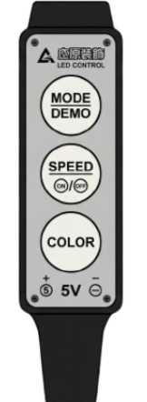
The 4pin 5v LED Controller is a compact and versatile component designed to manage the operation of 5V LED strips. It enables features such as dimming, color changing, and various lighting effects, making it ideal for decorative lighting, DIY projects, and smart home applications. This controller is compatible with most 5V RGB LED strips and provides an easy way to control lighting patterns with minimal setup.
Explore Projects Built with 4pin 5v Led Controller


Explore Projects Built with 4pin 5v Led Controller
Common Applications
- Decorative lighting for homes, offices, and events
- DIY electronics and hobbyist projects
- Smart home lighting systems
- Backlighting for TVs, monitors, or furniture
- Automotive interior lighting
Technical Specifications
Below are the key technical details for the 4pin 5v LED Controller:
| Parameter | Value |
|---|---|
| Operating Voltage | 5V DC |
| Maximum Current Output | 3A |
| Supported LED Types | RGB LED strips (common anode) |
| Control Method | PWM (Pulse Width Modulation) |
| Number of Pins | 4 |
| Dimensions | Varies by manufacturer |
Pin Configuration and Descriptions
The 4pin 5v LED Controller has the following pin configuration:
| Pin | Name | Description |
|---|---|---|
| 1 | VCC | Power input pin. Connect to a 5V DC power source. |
| 2 | GND | Ground pin. Connect to the ground of the power source and LED strip. |
| 3 | DATA | Data signal pin. Sends control signals to the LED strip for color and effects. |
| 4 | CLK | Clock signal pin. Synchronizes data transmission to the LED strip. |
Usage Instructions
How to Use the Component in a Circuit
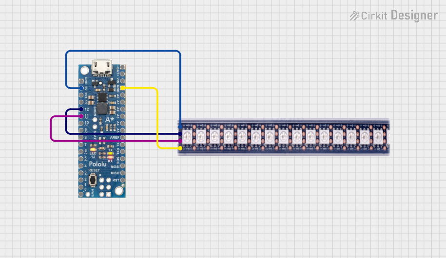
- Power Connection: Connect the VCC pin to a 5V DC power source and the GND pin to the ground of the same power source.
- LED Strip Connection: Connect the DATA and CLK pins to the corresponding input pins on the 5V RGB LED strip.
- Controller Input: Use a microcontroller (e.g., Arduino UNO) or a compatible remote control to send signals to the controller for managing LED behavior.
- Testing: Power on the circuit and test the LED strip for proper operation. Adjust settings as needed.
Important Considerations and Best Practices
- Ensure the power supply can provide sufficient current for the LED strip and controller (e.g., 3A for a fully lit RGB strip).
- Use proper wire gauges to handle the current without overheating.
- Avoid exceeding the maximum current rating of the controller to prevent damage.
- If using an Arduino UNO, ensure the DATA and CLK pins are connected to appropriate digital output pins.
Example Arduino Code
Below is an example of how to control the 4pin 5v LED Controller using an Arduino UNO:
// Include the necessary library for controlling LEDs
#include <Adafruit_NeoPixel.h>

// Define the pin numbers for DATA and CLK
#define DATA_PIN 6  // Connect to the DATA pin of the LED controller
#define CLK_PIN 7   // Connect to the CLK pin of the LED controller

// Define the number of LEDs in the strip
#define NUM_LEDS 30

// Create an instance of the Adafruit_NeoPixel library
Adafruit_NeoPixel strip = Adafruit_NeoPixel(NUM_LEDS, DATA_PIN, NEO_GRB + NEO_KHZ800);

void setup() {
  strip.begin();  // Initialize the LED strip
  strip.show();   // Turn off all LEDs initially
}

void loop() {
  // Example: Set all LEDs to red
  for (int i = 0; i < NUM_LEDS; i++) {
    strip.setPixelColor(i, strip.Color(255, 0, 0));  // Red color
  }
  strip.show();  // Update the LED strip with the new color
  delay(1000);   // Wait for 1 second

  // Example: Set all LEDs to green
  for (int i = 0; i < NUM_LEDS; i++) {
    strip.setPixelColor(i, strip.Color(0, 255, 0));  // Green color
  }
  strip.show();  // Update the LED strip with the new color
  delay(1000);   // Wait for 1 second

  // Example: Set all LEDs to blue
  for (int i = 0; i < NUM_LEDS; i++) {
    strip.setPixelColor(i, strip.Color(0, 0, 255));  // Blue color
  }
  strip.show();  // Update the LED strip with the new color
  delay(1000);   // Wait for 1 second
}
Troubleshooting and FAQs
Common Issues
LED Strip Not Lighting Up
- Cause: Incorrect wiring or insufficient power supply.
- Solution: Double-check all connections and ensure the power supply meets the current requirements.
Flickering LEDs
- Cause: Poor signal integrity or loose connections.
- Solution: Use shorter wires for DATA and CLK pins, and ensure all connections are secure.
Incorrect Colors Displayed
- Cause: Misconfigured LED type or incorrect wiring.
- Solution: Verify that the LED strip is compatible with the controller and check the wiring.
Controller Overheating
- Cause: Exceeding the maximum current rating.
- Solution: Reduce the number of LEDs or use a higher-rated controller.
FAQs
Q: Can I use this controller with a 12V LED strip?
A: No, this controller is designed specifically for 5V LED strips. Using it with a 12V strip may damage the controller or the LEDs.
Q: How many LEDs can this controller handle?
A: The maximum number of LEDs depends on the current draw of the strip. For example, if each LED draws 60mA, the controller can handle up to 50 LEDs (3A ÷ 0.06A).
Q: Can I control this component wirelessly?
A: Yes, if paired with a microcontroller that supports wireless communication (e.g., ESP8266 or ESP32), you can control the LEDs wirelessly.
Q: Do I need a resistor on the DATA line?
A: It is recommended to use a 330Ω resistor on the DATA line to improve signal integrity and protect the LEDs.
This concludes the documentation for the 4pin 5v LED Controller.