How to Use COPPER COIL - 30 TURNS: Examples, Pinouts, and Specs
Introduction
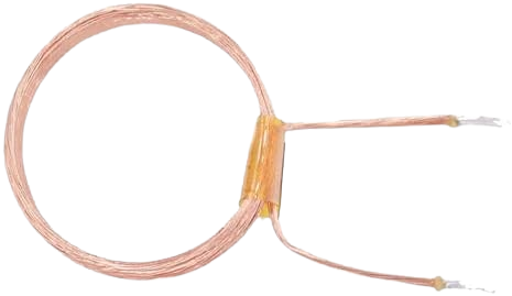
The COPPER COIL - 30 TURNS is a passive electronic component consisting of 30 turns of copper wire wound into a coil. It is primarily used to generate magnetic fields or induce electromotive force (EMF) in electrical circuits. This component is versatile and finds applications in inductors, transformers, electromagnets, and RF circuits.
Explore Projects Built with COPPER COIL - 30 TURNS

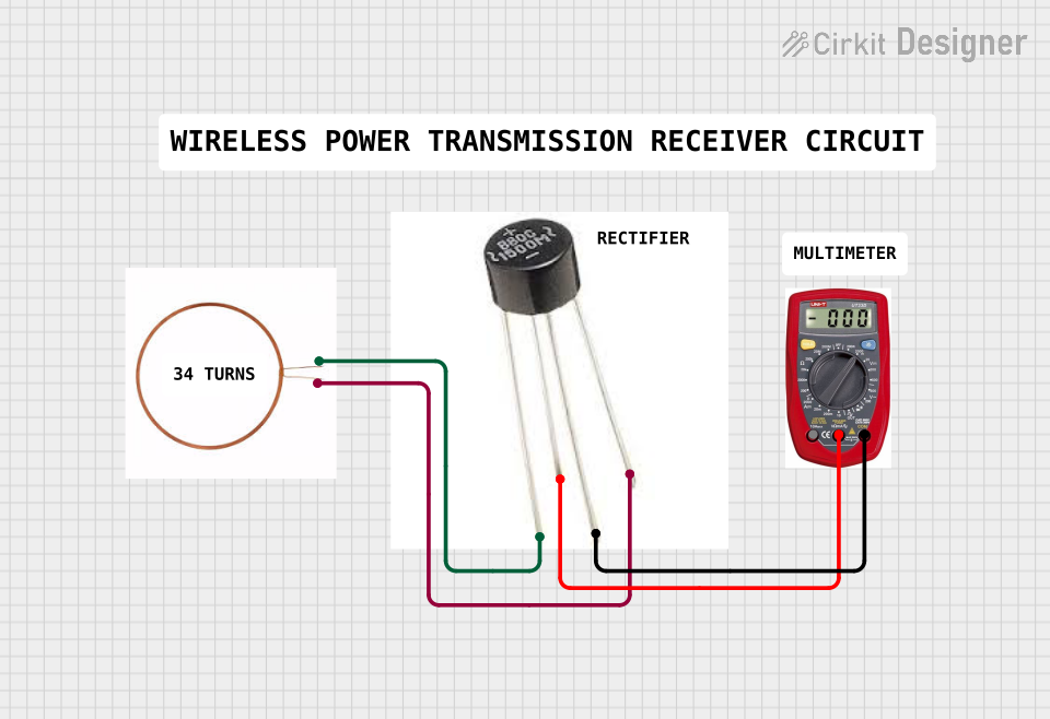
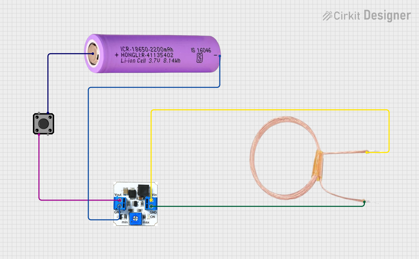

Explore Projects Built with COPPER COIL - 30 TURNS
Common Applications and Use Cases
- Inductors: Used in filters, oscillators, and energy storage applications.
- Transformers: For stepping up or stepping down voltage in AC circuits.
- Electromagnets: To create magnetic fields for mechanical actuation.
- Wireless Power Transfer: In resonant inductive coupling systems.
- Radio Frequency (RF) Circuits: For tuning and impedance matching.
Technical Specifications
Below are the key technical details for the COPPER COIL - 30 TURNS:
| Parameter | Value |
|---|---|
| Manufacturer | Default |
| Manufacturer Part ID | 30 TURNS |
| Number of Turns | 30 |
| Wire Material | Copper |
| Wire Gauge (AWG) | 24 AWG |
| Coil Diameter | 10 mm |
| Inductance (Approx.) | 10 µH (varies with core) |
| Maximum Current | 2 A |
| Resistance (DC) | 0.1 Ω |
| Operating Temperature | -40°C to +85°C |
Pin Configuration and Descriptions
The COPPER COIL - 30 TURNS has two terminals, as described below:
| Pin | Description |
|---|---|
| Pin 1 | Start of the copper winding |
| Pin 2 | End of the copper winding |
Usage Instructions
How to Use the Component in a Circuit
- Determine the Application: Identify whether the coil will be used as an inductor, transformer winding, or electromagnet.
- Connect the Terminals:
- Connect Pin 1 and Pin 2 to the circuit as required.
- Ensure proper polarity if used in conjunction with other inductive components.
- Select a Core (Optional): For applications requiring higher inductance, insert a ferromagnetic core into the coil.
- Verify Current and Voltage Ratings: Ensure the current through the coil does not exceed 2 A to prevent overheating.
Important Considerations and Best Practices
- Avoid Overheating: Prolonged operation at high currents may cause the coil to overheat. Use proper heat dissipation techniques if necessary.
- Minimize Signal Loss: For high-frequency applications, ensure the coil is properly shielded to reduce electromagnetic interference (EMI).
- Secure the Coil: Mount the coil securely to prevent mechanical vibrations or movement, which could affect performance.
- Use with Arduino UNO: The coil can be used with an Arduino UNO for applications like generating magnetic fields or detecting inductance changes.
Example Arduino Code: Measuring Inductance
The following code demonstrates how to measure the inductance of the COPPER COIL - 30 TURNS using an Arduino UNO and a simple LC circuit.
/*
  Inductance Measurement Example
  This code measures the resonant frequency of an LC circuit to calculate
  the inductance of the copper coil. Ensure the capacitor value is known.
*/

const float capacitorValue = 0.000001; // Capacitance in Farads (1 µF)
float frequency; // Resonant frequency in Hz
float inductance; // Inductance in Henries

void setup() {
  Serial.begin(9600); // Initialize serial communication
  Serial.println("Inductance Measurement Starting...");
}

void loop() {
  // Simulate frequency measurement (replace with actual sensor input)
  frequency = 100000; // Example frequency in Hz (replace with real data)

  // Calculate inductance using the formula: L = 1 / (4 * π² * f² * C)
  inductance = 1 / (4 * PI * PI * frequency * frequency * capacitorValue);

  // Print the calculated inductance
  Serial.print("Inductance: ");
  Serial.print(inductance * 1e6); // Convert to µH
  Serial.println(" µH");

  delay(1000); // Wait for 1 second before repeating
}
Notes:
- Replace the
frequencyvariable with actual frequency data from a sensor or measurement device. - Ensure the capacitor value is accurate for precise inductance calculations.
Troubleshooting and FAQs
Common Issues Users Might Face
Low Inductance Values:
- Cause: Incorrect core material or absence of a core.
- Solution: Use a ferromagnetic core to increase inductance.
Overheating:
- Cause: Exceeding the maximum current rating of 2 A.
- Solution: Reduce the current or improve heat dissipation.
Signal Interference:
- Cause: Electromagnetic interference (EMI) from nearby components.
- Solution: Use shielding or increase the distance between components.
Mechanical Instability:
- Cause: Loose mounting of the coil.
- Solution: Secure the coil with adhesive or mounting brackets.
FAQs
Q1: Can I use this coil for high-frequency applications?
A1: Yes, but ensure proper shielding to minimize EMI and signal loss.
Q2: How do I calculate the inductance of the coil?
A2: Use the formula ( L = \frac{1}{4 \pi^2 f^2 C} ), where ( f ) is the resonant frequency and ( C ) is the capacitance.
Q3: Can I use this coil without a core?
A3: Yes, but the inductance will be lower compared to using a ferromagnetic core.
Q4: What is the maximum voltage rating for this coil?
A4: The voltage rating depends on the insulation of the wire. For 24 AWG copper wire, it is typically around 300 V.
By following this documentation, users can effectively integrate the COPPER COIL - 30 TURNS into their projects and troubleshoot common issues.