How to Use Photo: Examples, Pinouts, and Specs
Introduction
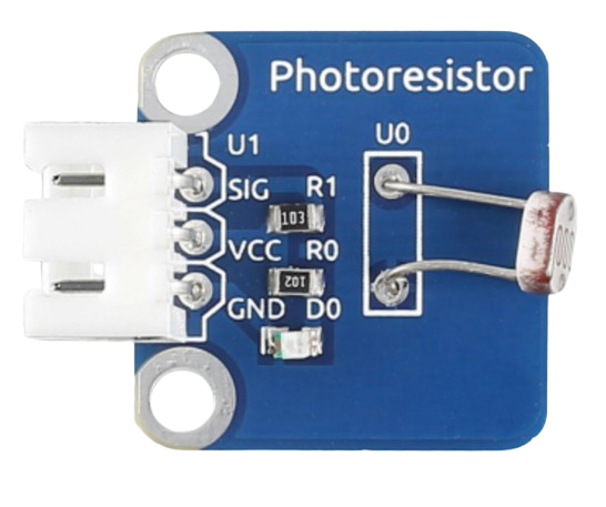
A photoresistor, also known as a light-dependent resistor (LDR), is a passive electronic component whose resistance decreases as the intensity of light falling on it increases. This property makes it an ideal choice for light-sensing applications. Photoresistors are widely used in devices such as automatic lighting systems, light meters, and alarm systems.
Explore Projects Built with Photo
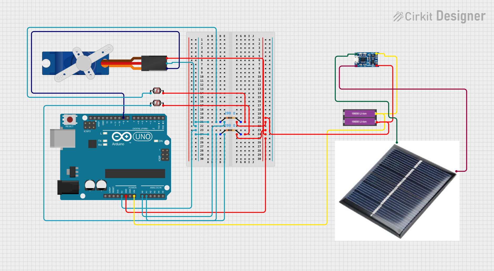
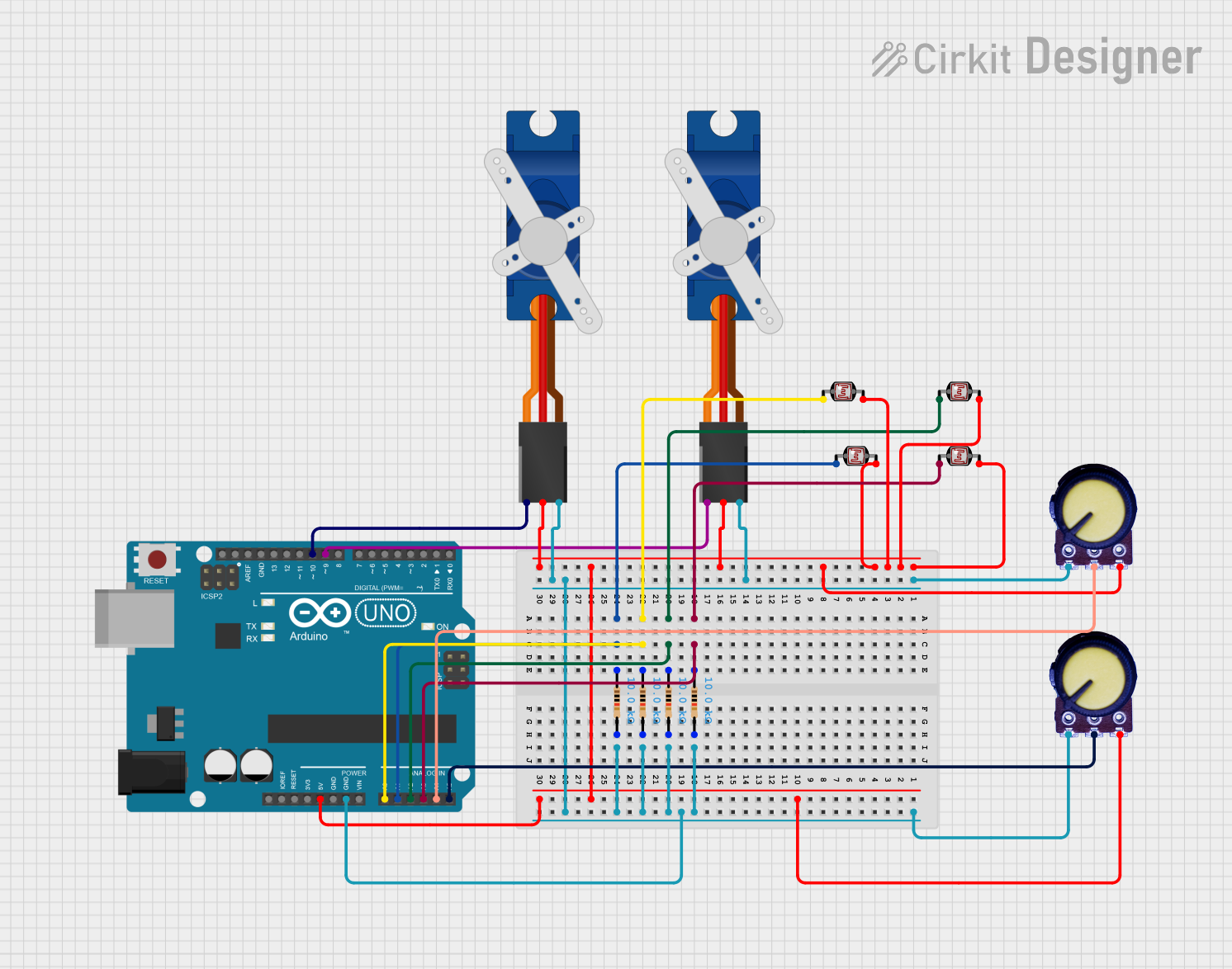
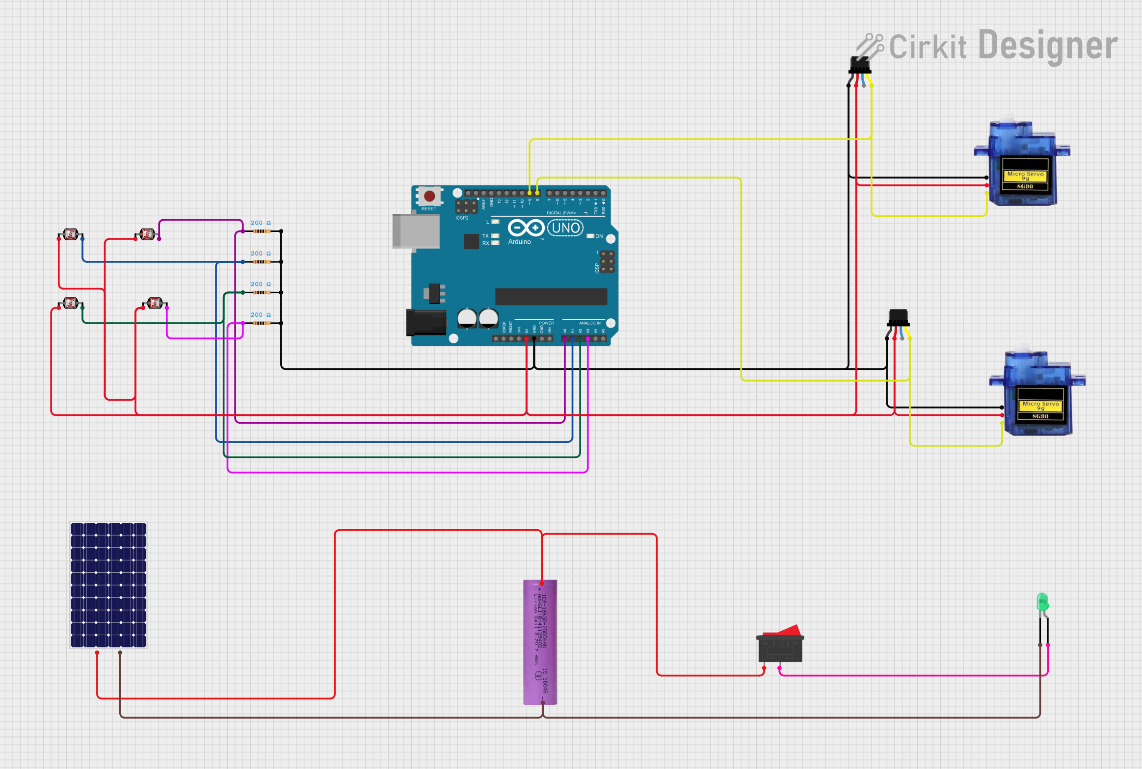
Explore Projects Built with Photo
Common Applications and Use Cases
- Automatic streetlights
- Light-sensitive alarms
- Brightness control in displays
- Solar tracking systems
- Optical encoders
Technical Specifications
Below are the general technical specifications for a typical photoresistor. Note that exact values may vary depending on the specific model or manufacturer.
| Parameter | Value |
|---|---|
| Resistance (Dark) | 1 MΩ to 10 MΩ |
| Resistance (Bright Light) | 1 kΩ to 10 kΩ |
| Maximum Voltage | 150 V |
| Power Dissipation | 100 mW |
| Response Time (Rise) | 20 ms to 30 ms |
| Response Time (Fall) | 30 ms to 50 ms |
| Operating Temperature | -30°C to +70°C |
| Spectral Peak Sensitivity | 540 nm (green light) |
Pin Configuration and Descriptions
A photoresistor typically has two terminals (no polarity), making it easy to integrate into circuits. Below is a description of its pins:
| Pin | Description |
|---|---|
| Pin 1 | Connects to one side of the circuit |
| Pin 2 | Connects to the other side of the circuit |
Usage Instructions
How to Use the Component in a Circuit
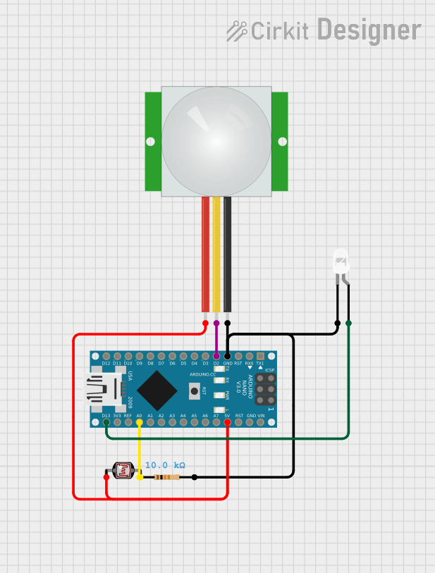
Basic Circuit Setup:
- Connect one terminal of the photoresistor to a voltage source (e.g., 5V).
- Connect the other terminal to a resistor (commonly 10 kΩ) in series, which is then connected to ground.
- The junction between the photoresistor and the resistor serves as the output voltage point, which varies with light intensity.
Interfacing with an Arduino UNO:
- Connect the output voltage point to an analog input pin (e.g., A0) on the Arduino UNO.
- Use the Arduino's
analogRead()function to measure the voltage and determine the light intensity.
Important Considerations and Best Practices
- Resistor Selection: Choose a pull-down resistor value that matches the expected light conditions for optimal sensitivity.
- Ambient Light: Ensure the photoresistor is shielded from unwanted light sources to avoid interference.
- Response Time: Note that photoresistors have a slower response time compared to photodiodes or phototransistors, making them unsuitable for high-speed applications.
- Voltage Ratings: Do not exceed the maximum voltage rating of the photoresistor to prevent damage.
Example Code for Arduino UNO
// Example code to read light intensity using a photoresistor and Arduino UNO

const int ldrPin = A0;  // Define the analog pin connected to the photoresistor
int ldrValue = 0;       // Variable to store the LDR reading

void setup() {
  Serial.begin(9600);   // Initialize serial communication at 9600 baud
}

void loop() {
  ldrValue = analogRead(ldrPin);  // Read the analog value from the LDR
  Serial.print("Light Intensity: ");
  Serial.println(ldrValue);       // Print the LDR value to the Serial Monitor

  delay(500);  // Wait for 500ms before the next reading
}
Troubleshooting and FAQs
Common Issues and Solutions
No Change in Output Voltage:
- Cause: Incorrect wiring or damaged photoresistor.
- Solution: Double-check the circuit connections and ensure the photoresistor is functional.
Inconsistent Readings:
- Cause: Electrical noise or unstable light source.
- Solution: Use a capacitor (e.g., 0.1 µF) across the photoresistor to filter noise and ensure a stable light source.
Low Sensitivity:
- Cause: Incorrect pull-down resistor value.
- Solution: Adjust the resistor value to better match the light conditions.
Component Overheating:
- Cause: Exceeding the power dissipation or voltage rating.
- Solution: Ensure the voltage and current are within the specified limits.
FAQs
Q1: Can a photoresistor detect infrared light?
A: Most photoresistors are sensitive to visible light, particularly around 540 nm. However, some models are designed to detect infrared light. Check the datasheet for spectral sensitivity.
Q2: How do I increase the accuracy of light measurements?
A: Use an analog-to-digital converter (ADC) with higher resolution and ensure the photoresistor is shielded from ambient light interference.
Q3: Can I use a photoresistor in outdoor applications?
A: Yes, but ensure it is protected from environmental factors like moisture and extreme temperatures. Use a weatherproof enclosure if necessary.
Q4: What is the lifespan of a photoresistor?
A: Photoresistors have a long lifespan under normal operating conditions, but prolonged exposure to high-intensity light or heat may degrade their performance over time.