How to Use Serial Bus Servo: Examples, Pinouts, and Specs
Introduction
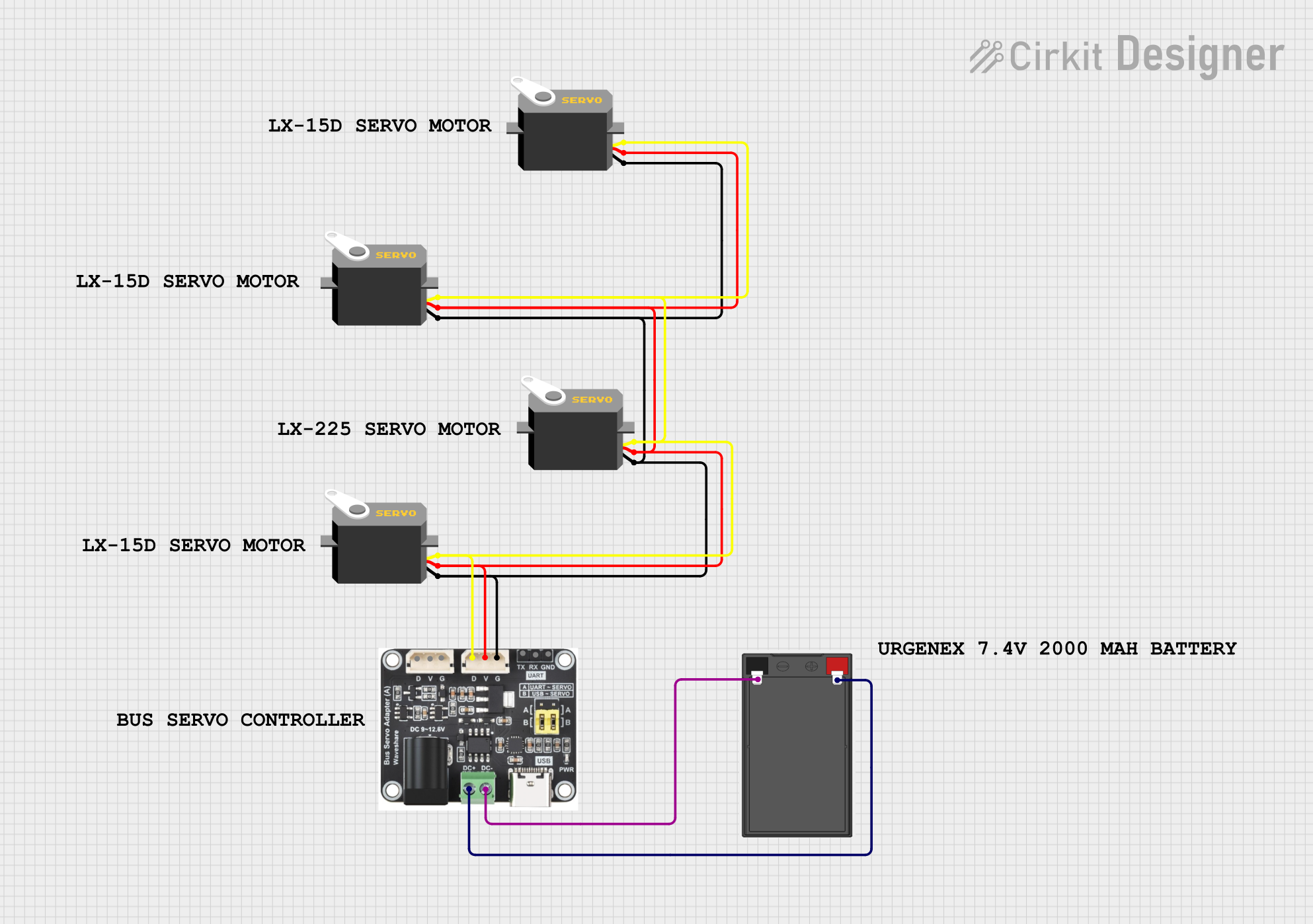
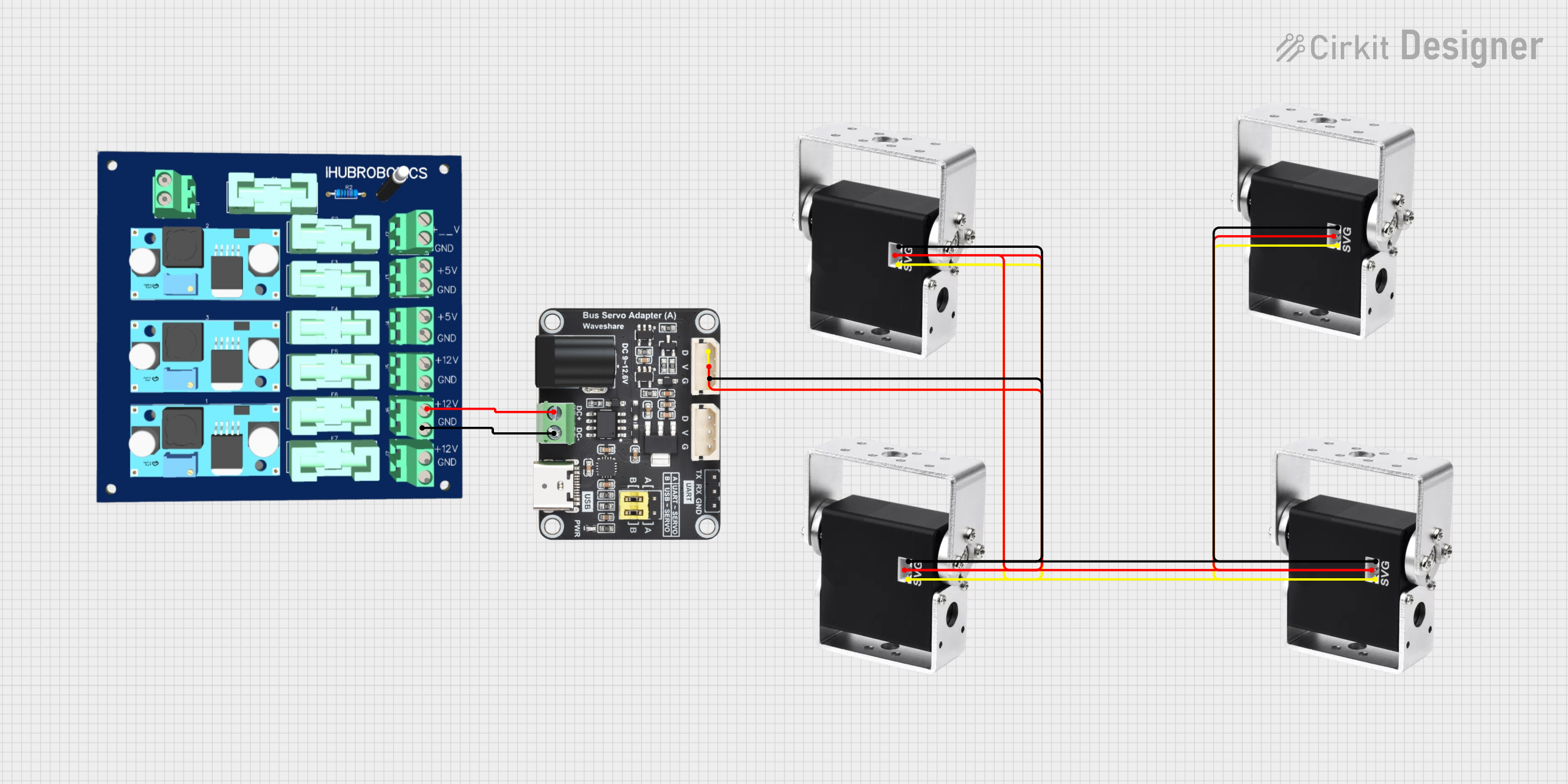
The Serial Bus Servo by Waveshare is a sophisticated actuator designed for precise control and synchronization in various robotic and automation applications. Unlike traditional servos that use a PWM signal for position control, the Serial Bus Servo communicates using a serial bus protocol, which allows for multiple servos to be daisy-chained and controlled via a single communication line. This feature simplifies wiring and enables complex motion control scenarios in projects such as robotic arms, animatronics, and custom automation systems.
Explore Projects Built with Serial Bus Servo


Explore Projects Built with Serial Bus Servo
Common Applications and Use Cases
- Robotic arms and manipulators
- Animatronics and special effects
- Custom automation systems
- Educational platforms for robotics
- Hobbyist projects requiring precise motion control
Technical Specifications
Key Technical Details
- Operating Voltage: 6.0V - 8.4V
- Stall Torque: (specify torque at 6.0V and 8.4V)
- Operating Speed: (specify speed at 6.0V and 8.4V)
- Communication Protocol: Serial Bus Protocol
- Resolution: 0.24 degrees
- Control Angle: 0 to 300 degrees (adjustable)
- Maximum Holding Torque: (specify value)
- Dimensions: (specify dimensions)
- Weight: (specify weight)
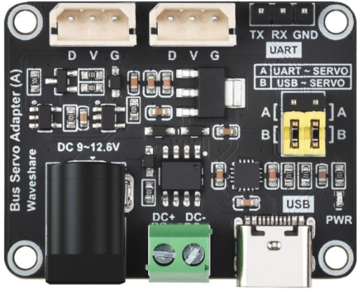
Pin Configuration and Descriptions
| Pin Number | Description | Notes |
|---|---|---|
| 1 | Ground (GND) | Connect to system ground |
| 2 | Power (V+) | Operating voltage 6.0V - 8.4V |
| 3 | Control/Data (TX/RX) | Serial communication line |
Usage Instructions
How to Use the Component in a Circuit
Power Supply: Ensure that the power supply is within the operating voltage range of the servo. Connect the positive lead to the V+ pin and the ground lead to the GND pin.
Data Connection: Connect the control/data line to a microcontroller or a serial bus controller capable of communicating using the servo's protocol.
Addressing: Each servo must be assigned a unique address if multiple servos are daisy-chained on the same bus.
Command Structure: Familiarize yourself with the command structure for position, speed, and torque control as specified by Waveshare.
Important Considerations and Best Practices
- Avoid exceeding the recommended voltage as it may damage the servo.
- Ensure that the servo's mounting and load are within its mechanical limits.
- Use a twisted pair cable for the data line to reduce interference.
- Implement proper error handling in your software to address communication failures.
Example Code for Arduino UNO
#include <SoftwareSerial.h>

SoftwareSerial servoSerial(10, 11); // RX, TX

void setup() {
  servoSerial.begin(9600); // Initialize serial communication at 9600 baud rate
}

void loop() {
  // Example command to set servo position
  // Replace 'servoID' with the actual ID of your servo
  // Replace 'position' with the desired position value
  int servoID = 1;
  int position = 512; // Midpoint of the servo range
  setServoPosition(servoID, position);
  delay(1000); // Wait for 1 second
}

// Function to construct and send a position command to the servo
void setServoPosition(int id, int position) {
  byte cmd[] = {0xFF, 0xFF, id, 5, 3, (position & 0xFF), (position >> 8)};
  servoSerial.write(cmd, sizeof(cmd));
  // Calculate and send the checksum byte here (not shown for brevity)
}

// Remember to calculate the checksum as per the servo's communication protocol
Note: The example code provided is a basic illustration of how to communicate with the Serial Bus Servo using an Arduino UNO. You will need to refer to the Waveshare documentation for the complete communication protocol, including how to calculate the checksum for commands.
Troubleshooting and FAQs
Common Issues Users Might Face
- Servo not responding: Check the power supply and connections. Ensure that the servo ID and baud rate match your setup.
- Erratic movements: Verify that the command structure and checksum are correct. Also, check for electrical noise or interference on the data line.
- Overheating: Ensure that the servo is not overloaded and that the operating voltage is within the specified range.
Solutions and Tips for Troubleshooting
- Double-check wiring and connections for any loose or incorrect connections.
- Use a logic analyzer or oscilloscope to verify the integrity of the signals being sent to the servo.
- Implement a timeout mechanism in your software to recover from communication failures.
FAQs:
Q: Can I control the speed of the servo? A: Yes, the Serial Bus Servo protocol typically includes commands for speed control.
Q: How many servos can I daisy-chain together? A: This depends on the power supply capacity and the communication protocol limits. Refer to the Waveshare documentation for specific details.
Q: What should I do if the servo is not holding its position? A: Check the torque settings and ensure that the servo is not being physically obstructed or overloaded.