
How to Use MCB TOMZN tob1z 63 c40 MCB PV: Examples, Pinouts, and Specs
 Design with MCB TOMZN tob1z 63 c40 MCB PV in Cirkit Designer
Introduction
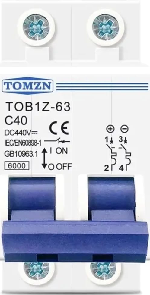
The MCB TOMZN TOB1Z 63 C40 is a miniature circuit breaker (MCB) specifically designed for photovoltaic (PV) applications. It is rated for a maximum current of 63A and features a C40 trip curve, making it ideal for protecting solar power systems from overcurrent conditions. This MCB ensures reliable operation and safety in both residential and commercial PV installations.
Explore Projects Built with MCB TOMZN tob1z 63 c40 MCB PV
 Open Project in Cirkit Designer
 Open Project in Cirkit Designer
 Open Project in Cirkit Designer
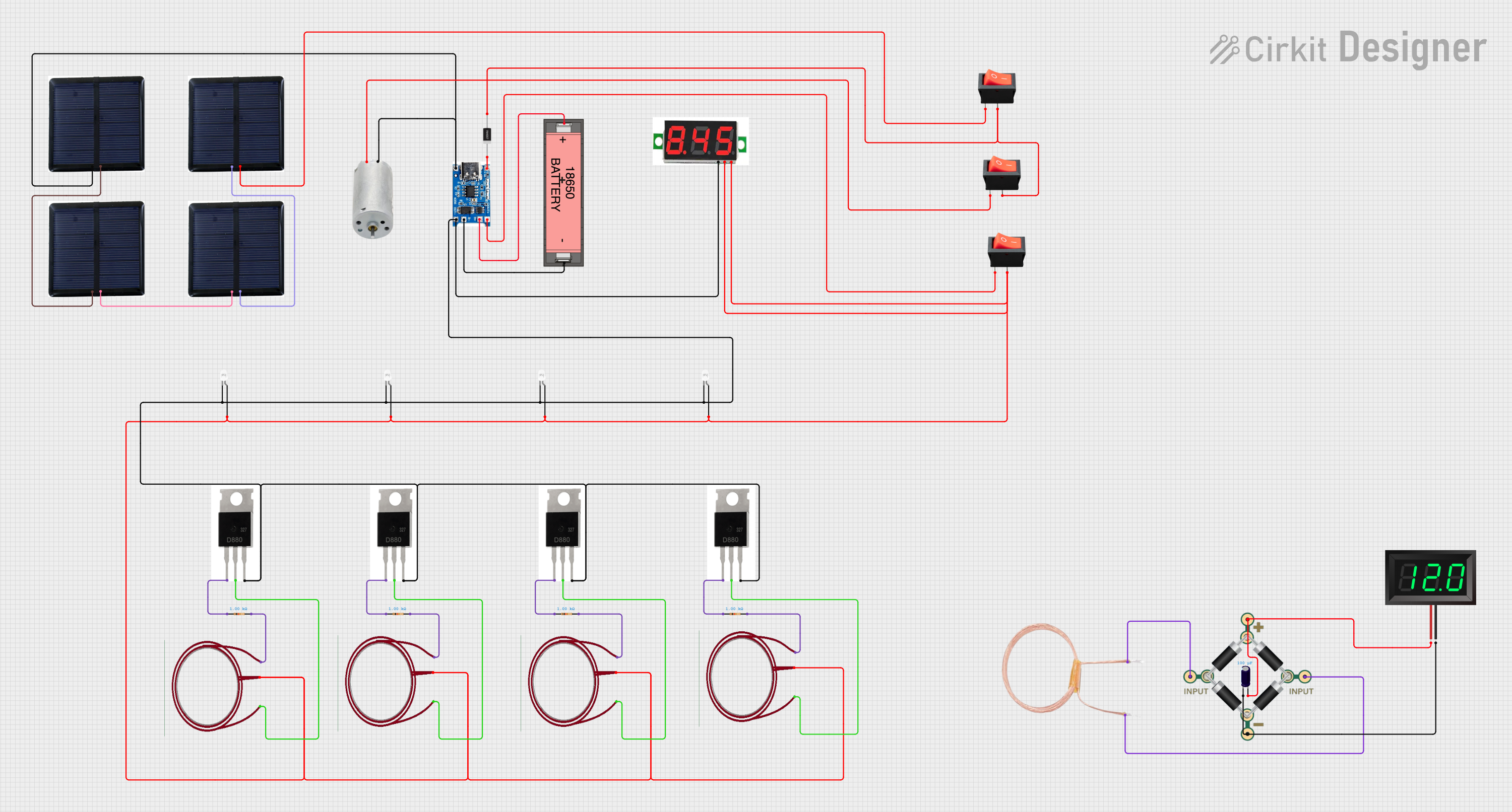 Open Project in Cirkit Designer
Explore Projects Built with MCB TOMZN tob1z 63 c40 MCB PV
Open Project in Cirkit DesignerOpen Project in Cirkit DesignerOpen Project in Cirkit DesignerOpen Project in Cirkit DesignerCommon Applications and Use Cases
- Overcurrent protection in photovoltaic (solar) systems
- DC circuit protection in solar inverters and charge controllers
- Safety isolation for solar panel arrays
- Protection of battery storage systems in renewable energy setups
Technical Specifications
Key Technical Details
| Parameter | Specification |
|---|---|
| Rated Current (In) | 63A |
| Trip Curve | C40 |
| Rated Voltage (Un) | 1000V DC |
| Number of Poles | 2P (Double Pole) |
| Breaking Capacity | 6kA |
| Operating Temperature | -25°C to +70°C |
| Mounting Type | DIN Rail (Standard 35mm) |
| Standards Compliance | IEC/EN 60947-2, IEC/EN 60898-1 |
Pin Configuration and Descriptions
The MCB TOMZN TOB1Z 63 C40 has two input terminals and two output terminals, as described below:
| Terminal | Description |
|---|---|
| L+ | Positive input from the PV system |
| L- | Negative input from the PV system |
| OUT+ | Positive output to the load |
| OUT- | Negative output to the load |
Usage Instructions
How to Use the Component in a Circuit
- Mounting the MCB: Securely install the MCB on a standard 35mm DIN rail in your distribution box or enclosure.
- Wiring:
- Connect the positive and negative DC inputs from the photovoltaic system to the
L+andL-terminals, respectively. - Connect the positive and negative DC outputs to the load (e.g., inverter or charge controller) to the
OUT+andOUT-terminals. - Ensure all connections are tight and secure to prevent arcing or overheating.
- Connect the positive and negative DC inputs from the photovoltaic system to the
- Operation:
- Switch the MCB to the "ON" position to allow current flow.
- In case of an overcurrent or short circuit, the MCB will trip to the "OFF" position, interrupting the circuit.
Important Considerations and Best Practices
- Voltage Rating: Ensure the total voltage of the PV system does not exceed the MCB's rated voltage of 1000V DC.
- Current Rating: Verify that the total current in the circuit does not exceed the MCB's rated current of 63A.
- Trip Curve: The C40 trip curve is suitable for circuits with moderate inrush currents, such as those in PV systems. Ensure compatibility with your specific application.
- Polarity: Maintain correct polarity when connecting the MCB to avoid damage or malfunction.
- Environmental Conditions: Install the MCB in a dry, well-ventilated area to prevent moisture or overheating.
Example Connection with an Arduino UNO
While the MCB itself is not directly connected to an Arduino UNO, it can be used in a PV system that powers an Arduino-based project. Below is an example of how to monitor the MCB's status using an Arduino:
// Example code to monitor the status of the MCB using an Arduino UNO
// This assumes the MCB's output is connected to a digital input pin on the Arduino.

const int mcbStatusPin = 2; // Pin connected to the MCB output
const int ledPin = 13;      // Built-in LED to indicate MCB status

void setup() {
  pinMode(mcbStatusPin, INPUT); // Set the MCB status pin as input
  pinMode(ledPin, OUTPUT);      // Set the LED pin as output
  Serial.begin(9600);           // Initialize serial communication
}

void loop() {
  int mcbStatus = digitalRead(mcbStatusPin); // Read the MCB status

  if (mcbStatus == HIGH) {
    // If the MCB is ON, turn off the LED and print status
    digitalWrite(ledPin, LOW);
    Serial.println("MCB is ON: Circuit is active.");
  } else {
    // If the MCB is OFF, turn on the LED and print status
    digitalWrite(ledPin, HIGH);
    Serial.println("MCB is OFF: Circuit is interrupted.");
  }

  delay(1000); // Wait for 1 second before checking again
}
Troubleshooting and FAQs
Common Issues and Solutions
| Issue | Possible Cause | Solution |
|---|---|---|
| MCB trips frequently | Overcurrent or short circuit in the PV system | Check the circuit for faults or overloads. |
| MCB does not trip during a fault | Fault current is below the trip threshold | Verify the current rating and trip curve. |
| Loose connections | Improperly tightened terminals | Re-tighten all connections securely. |
| Overheating of the MCB | High ambient temperature or poor ventilation | Improve ventilation or relocate the MCB. |
FAQs
Can this MCB be used for AC circuits?
- No, this MCB is specifically designed for DC circuits, particularly in photovoltaic systems.
What does the C40 trip curve mean?
- The C40 trip curve indicates that the MCB will trip when the current exceeds 5 to 10 times the rated current (63A) for a short duration. This makes it suitable for circuits with moderate inrush currents.
How do I reset the MCB after it trips?
- First, identify and resolve the cause of the trip (e.g., overcurrent or short circuit). Then, switch the MCB to the "OFF" position and back to the "ON" position.
Can this MCB be used in outdoor installations?
- The MCB itself is not weatherproof. If used outdoors, it must be installed in a weatherproof enclosure.
By following this documentation, users can safely and effectively integrate the MCB TOMZN TOB1Z 63 C40 into their photovoltaic systems.