Cirkit Designer
Your all-in-one circuit design IDE
Home /
Component Documentation
How to Use A988 DRIVER : Examples, Pinouts, and Specs
Introduction
The A988 DRIVER is an integrated circuit designed to drive transistors or other high-power discrete components. It is commonly used in applications requiring amplification and precise control of current flow through a load, such as in motor control circuits, power regulators, and audio amplifiers.
Explore Projects Built with A988 DRIVER
Raspberry Pi Pico W Controlled Bipolar Stepper Motor Driver
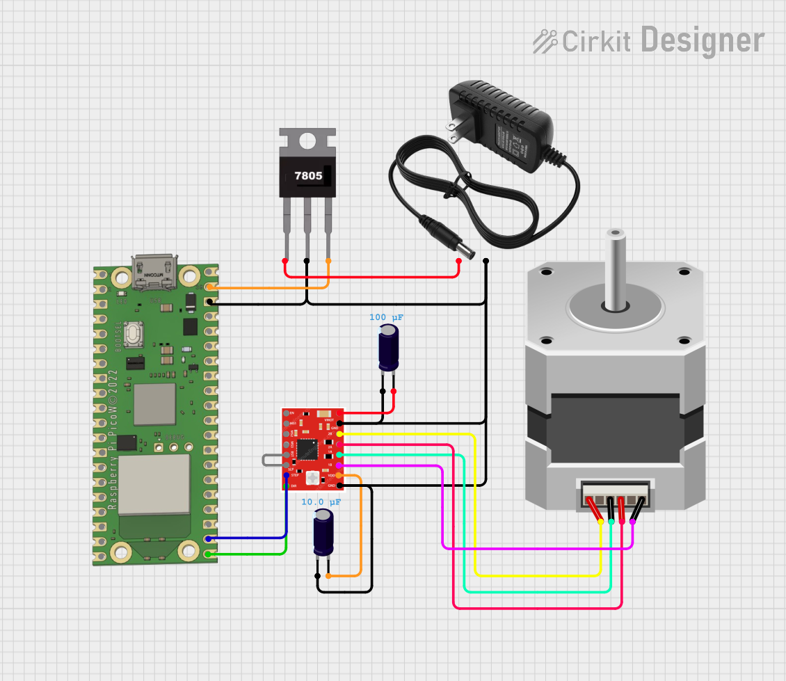
This circuit is designed to control a bipolar stepper motor using a Raspberry Pi Pico W microcontroller and an A988 stepper motor driver. The 7805 voltage regulator takes input from a 12V power supply to provide a stable 5V output for the Raspberry Pi Pico W and the logic side of the A988 driver. Capacitors are used for voltage smoothing on the input and output of the voltage regulator, and the A988 driver's VMOT pin is directly connected to the 12V supply for motor power.
ESP32 and A988 Driver Controlled NEMA 17 Stepper Motor System
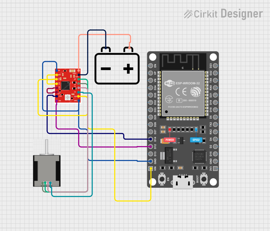
This circuit uses an ESP32 microcontroller to control a NEMA 17 stepper motor via an A988 driver. The ESP32 sends step and direction signals to the driver, which in turn powers and controls the stepper motor's movement. A 12V battery supplies power to the driver and motor.
Arduino Mega 2560-Controlled Stepper Motors with RFID Access and Traffic Light Indication

This circuit controls two 28BYJ-48 stepper motors using A4988 stepper motor driver carriers, interfaced with an Arduino Mega 2560 microcontroller. It features an RFID-RC522 module for RFID reading, a 16x4 LCD display with I2C interface for user interaction, and a piezo speaker for audio feedback. Additionally, there is a traffic light module controlled by the Arduino, and a 48V to 5V converter to step down voltage for the logic levels. The power supply provides 12V to the motor drivers and is connected to a standard power outlet.
RFID-Activated Traffic Light Controller with Auditory Feedback Using Arduino Mega

This circuit is designed to control two 28BYJ-48 stepper motors using A4988 stepper motor driver carriers, with an Arduino Mega 2560 as the central microcontroller. It includes an RFID-RC522 module for RFID reading, an LCD display for user interface, and a traffic light and piezo speaker for visual and audio signaling. The circuit is powered by a 12V 5A power supply, which is stepped down to 5V for logic level components, and it interfaces with a power outlet for AC to DC conversion.
Explore Projects Built with A988 DRIVER
Raspberry Pi Pico W Controlled Bipolar Stepper Motor Driver
This circuit is designed to control a bipolar stepper motor using a Raspberry Pi Pico W microcontroller and an A988 stepper motor driver. The 7805 voltage regulator takes input from a 12V power supply to provide a stable 5V output for the Raspberry Pi Pico W and the logic side of the A988 driver. Capacitors are used for voltage smoothing on the input and output of the voltage regulator, and the A988 driver's VMOT pin is directly connected to the 12V supply for motor power.
ESP32 and A988 Driver Controlled NEMA 17 Stepper Motor System
This circuit uses an ESP32 microcontroller to control a NEMA 17 stepper motor via an A988 driver. The ESP32 sends step and direction signals to the driver, which in turn powers and controls the stepper motor's movement. A 12V battery supplies power to the driver and motor.
Arduino Mega 2560-Controlled Stepper Motors with RFID Access and Traffic Light Indication
This circuit controls two 28BYJ-48 stepper motors using A4988 stepper motor driver carriers, interfaced with an Arduino Mega 2560 microcontroller. It features an RFID-RC522 module for RFID reading, a 16x4 LCD display with I2C interface for user interaction, and a piezo speaker for audio feedback. Additionally, there is a traffic light module controlled by the Arduino, and a 48V to 5V converter to step down voltage for the logic levels. The power supply provides 12V to the motor drivers and is connected to a standard power outlet.
RFID-Activated Traffic Light Controller with Auditory Feedback Using Arduino Mega
This circuit is designed to control two 28BYJ-48 stepper motors using A4988 stepper motor driver carriers, with an Arduino Mega 2560 as the central microcontroller. It includes an RFID-RC522 module for RFID reading, an LCD display for user interface, and a traffic light and piezo speaker for visual and audio signaling. The circuit is powered by a 12V 5A power supply, which is stepped down to 5V for logic level components, and it interfaces with a power outlet for AC to DC conversion.
Common Applications and Use Cases
- Stepper motor driving
- DC motor control
- Power regulation modules
- Audio amplification systems
Technical Specifications
Key Technical Details
- Operating Voltage Range: 3.0V to 30V
- Output Current: Up to 2A (with proper heat sinking)
- Logic Input Voltage Range: 2.5V to 5.5V
- Thermal Shutdown Protection: Yes
- Under Voltage Lockout: Yes
- Cross-Conduction Protection: Yes
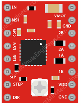
Pin Configuration and Descriptions
| Pin Number | Name | Description |
|---|---|---|
| 1 | Vcc | Power supply voltage; connects to the positive voltage supply |
| 2 | GND | Ground; connects to the system ground |
| 3 | IN1 | Logic input 1; controls the output state |
| 4 | OUT1 | Output 1; connects to one end of the load |
| 5 | IN2 | Logic input 2; controls the output state |
| 6 | OUT2 | Output 2; connects to the other end of the load |
| 7 | EN | Enable input; when low, disables both outputs |
| 8 | FAULT | Fault indication output; goes low to indicate an error condition |
Usage Instructions
How to Use the A988 DRIVER in a Circuit
- Connect Vcc to a suitable power supply (3.0V to 30V).
- Connect GND to the system ground.
- Connect IN1 and IN2 to the logic control signals (2.5V to 5.5V).
- Connect OUT1 and OUT2 to the load you wish to drive.
- Optionally, connect EN to a logic signal to enable or disable the outputs.
- Monitor the FAULT pin to detect any error conditions.
Important Considerations and Best Practices
- Always ensure that the power supply does not exceed the maximum voltage rating.
- Provide adequate heat sinking to deal with power dissipation, especially at higher output currents.
- Use flyback diodes when driving inductive loads to protect the driver from voltage spikes.
- Ensure that the logic input voltage is compatible with your control source.
- Do not exceed the maximum current rating to prevent damage to the device.
Troubleshooting and FAQs
Common Issues Users Might Face
- Overheating: Ensure proper heat sinking and airflow around the A988 DRIVER.
- Unexpected Behavior: Verify that the logic input signals are within the specified range and that the power supply is stable.
- No Output: Check the EN pin to ensure the device is enabled and the FAULT pin for any error conditions.
Solutions and Tips for Troubleshooting
- If overheating occurs, reduce the load current or improve heat dissipation.
- For unexpected behavior, double-check wiring and signal levels.
- If there is no output, ensure that the EN pin is high and there are no faults indicated by the FAULT pin.
FAQs
Q: Can the A988 DRIVER be used with an Arduino UNO?
- A: Yes, the A988 DRIVER can be interfaced with an Arduino UNO using digital I/O pins.
Q: What is the maximum current the A988 DRIVER can handle?
- A: The A988 DRIVER can handle up to 2A with proper heat sinking.
Q: How do I know if the A988 DRIVER is in a fault state?
- A: The FAULT pin will be driven low if there is a fault condition.
Example Arduino UNO Code
// Example code to control the A988 DRIVER with an Arduino UNO

const int in1Pin = 2; // IN1 connected to digital pin 2
const int in2Pin = 3; // IN2 connected to digital pin 3
const int enPin = 4;  // EN connected to digital pin 4

void setup() {
  pinMode(in1Pin, OUTPUT);
  pinMode(in2Pin, OUTPUT);
  pinMode(enPin, OUTPUT);

  // Enable the A988 DRIVER
  digitalWrite(enPin, HIGH);
}

void loop() {
  // Set IN1 high and IN2 low to drive the load in one direction
  digitalWrite(in1Pin, HIGH);
  digitalWrite(in2Pin, LOW);
  delay(1000); // Wait for 1 second

  // Set IN1 low and IN2 high to drive the load in the opposite direction
  digitalWrite(in1Pin, LOW);
  digitalWrite(in2Pin, HIGH);
  delay(1000); // Wait for 1 second
}
Remember to adjust the pin numbers as per your circuit configuration and ensure that the logic voltage levels are compatible with the Arduino UNO.