How to Use A6 GSM & GPRS module: Examples, Pinouts, and Specs
Introduction
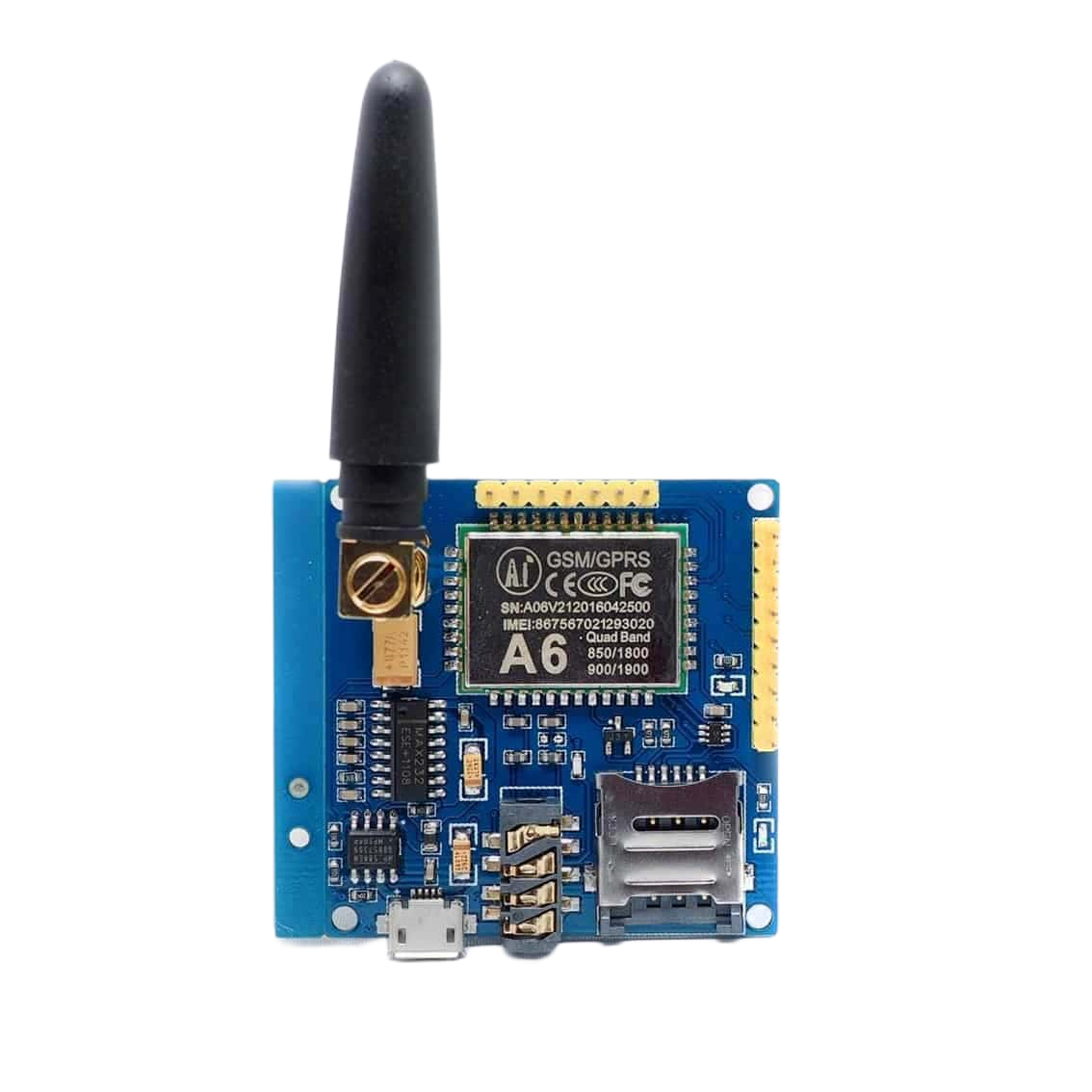
The A6 GSM & GPRS module, manufactured by Ai-Thinker, is a compact and cost-effective communication module designed to enable devices to connect to GSM networks. It supports voice calls, SMS messaging, and GPRS data transmission, making it an ideal choice for IoT applications, remote monitoring, and control systems. The module operates on quad-band frequencies, ensuring compatibility with GSM networks worldwide.
Explore Projects Built with A6 GSM & GPRS module
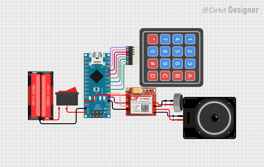
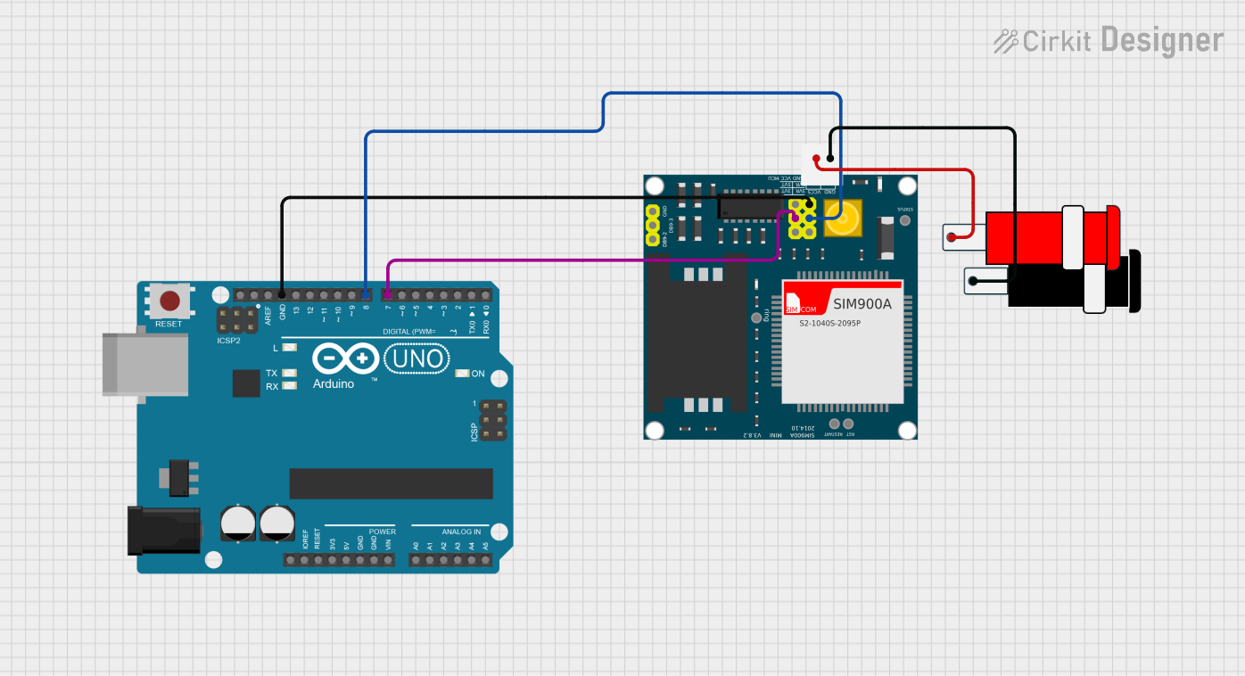
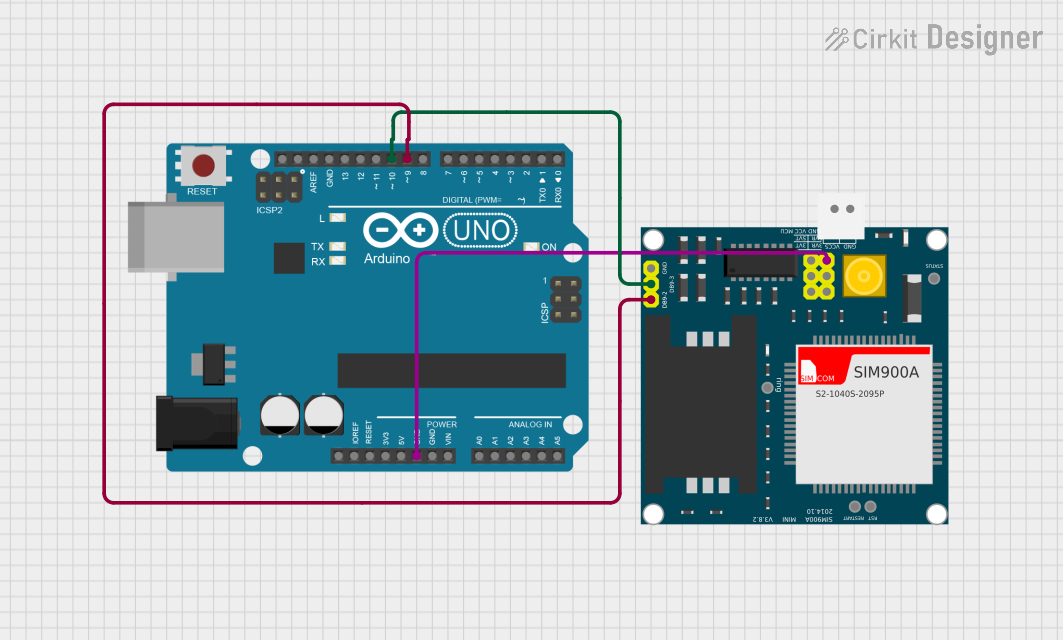

Explore Projects Built with A6 GSM & GPRS module
Common Applications
- IoT devices for remote monitoring and control
- Smart home automation systems
- GPS tracking and fleet management
- Wireless data transmission for industrial applications
- SMS-based alert and notification systems
Technical Specifications
The following table outlines the key technical details of the A6 GSM & GPRS module:
| Parameter | Specification |
|---|---|
| Manufacturer | Ai-Thinker |
| Part ID | A6 Quad-band GPRS/GSM |
| Operating Voltage | 3.3V to 4.2V (Typical: 4.0V) |
| Operating Current | Idle: ~3mA, Active: ~250mA, Peak: ~2A |
| Frequency Bands | GSM 850/900/1800/1900 MHz (Quad-band) |
| Communication Protocols | GSM, GPRS (Class 10) |
| Data Rate (GPRS) | Uplink: 85.6 kbps, Downlink: 85.6 kbps |
| Operating Temperature | -40°C to +85°C |
| Dimensions | 22.8mm x 16.8mm x 2.5mm |
Pin Configuration and Descriptions
The A6 module has a total of 24 pins. Below is the pinout and description:
| Pin Number | Pin Name | Description |
|---|---|---|
| 1 | VCC | Power supply input (3.3V to 4.2V) |
| 2 | GND | Ground |
| 3 | TXD | UART Transmit (connect to RX of microcontroller) |
| 4 | RXD | UART Receive (connect to TX of microcontroller) |
| 5 | NET | Network status indicator (blinks to show status) |
| 6 | RST | Reset pin (active low) |
| 7 | MIC+ | Microphone positive input |
| 8 | MIC- | Microphone negative input |
| 9 | SPK+ | Speaker positive output |
| 10 | SPK- | Speaker negative output |
| 11-24 | NC | Not connected |
Usage Instructions
How to Use the A6 GSM & GPRS Module in a Circuit
- Power Supply: Ensure the module is powered with a stable voltage between 3.3V and 4.2V. A 4.0V power source is recommended for optimal performance. Use a capacitor (e.g., 1000µF) near the power pins to handle peak current demands.
- UART Communication: Connect the TXD and RXD pins of the module to the RX and TX pins of your microcontroller, respectively. Use a logic level converter if your microcontroller operates at 5V logic.
- Antenna Connection: Attach a GSM antenna to the module's antenna connector to ensure proper signal reception.
- SIM Card: Insert a standard SIM card into the module's SIM card slot. Ensure the SIM card is activated and has sufficient balance for calls, SMS, or data usage.
- Network Status: Monitor the NET pin to check the module's network status. The blinking pattern indicates the connection state:
- Fast blinking: Searching for network
- Slow blinking: Connected to network
Important Considerations and Best Practices
- Use a stable power supply capable of providing up to 2A during peak current demands.
- Place the module away from high-frequency noise sources to avoid interference.
- Ensure proper grounding to minimize noise and improve signal quality.
- Use appropriate AT commands to configure the module for your application.
Example: Connecting the A6 Module to an Arduino UNO
Below is an example of how to send an SMS using the A6 module with an Arduino UNO:
Circuit Connections
| A6 Pin | Arduino UNO Pin |
|---|---|
| VCC | 5V (via a 4.0V regulator) |
| GND | GND |
| TXD | Pin 10 (SoftwareSerial RX) |
| RXD | Pin 11 (SoftwareSerial TX) |
Arduino Code
#include <SoftwareSerial.h>

// Define RX and TX pins for SoftwareSerial
SoftwareSerial A6Serial(10, 11); // RX = Pin 10, TX = Pin 11

void setup() {
  // Initialize serial communication with the A6 module
  A6Serial.begin(9600); // A6 module default baud rate is 9600
  Serial.begin(9600);   // For debugging via Serial Monitor

  // Wait for the module to initialize
  delay(5000);
  Serial.println("Initializing A6 module...");

  // Send AT command to check communication
  A6Serial.println("AT");
  delay(1000);
  while (A6Serial.available()) {
    Serial.write(A6Serial.read()); // Print A6 response to Serial Monitor
  }

  // Set SMS text mode
  A6Serial.println("AT+CMGF=1"); // Set SMS mode to text
  delay(1000);

  // Send SMS
  A6Serial.println("AT+CMGS=\"+1234567890\""); // Replace with recipient's phone number
  delay(1000);
  A6Serial.println("Hello from A6 GSM module!"); // SMS content
  delay(1000);
  A6Serial.write(26); // Send Ctrl+Z to indicate end of message
  delay(5000);

  Serial.println("SMS sent!");
}

void loop() {
  // Continuously check for incoming data from the A6 module
  if (A6Serial.available()) {
    Serial.write(A6Serial.read());
  }
}
Troubleshooting and FAQs
Common Issues and Solutions
Module Not Responding to AT Commands
- Ensure the module is powered correctly and the SIM card is inserted.
- Check the UART connections (TXD and RXD) and ensure they are not swapped.
- Verify the baud rate (default is 9600).
No Network Connection
- Check the antenna connection and ensure it is securely attached.
- Verify that the SIM card is activated and has network coverage.
- Place the module in an area with good GSM signal strength.
High Power Consumption
- Use a power supply capable of providing up to 2A during peak usage.
- Add a decoupling capacitor (e.g., 1000µF) near the power pins.
SMS Not Sending
- Ensure the SIM card has sufficient balance for sending SMS.
- Verify the recipient's phone number format (e.g., include country code).
FAQs
Can the A6 module be used for internet access?
- Yes, the A6 module supports GPRS for basic internet access. Use AT commands like
AT+HTTPto configure HTTP requests.
- Yes, the A6 module supports GPRS for basic internet access. Use AT commands like
What is the maximum distance for UART communication?
- UART communication is typically reliable up to a few meters. For longer distances, consider using RS-485 or other communication protocols.
Does the module support 5V logic?
- No, the A6 module operates at 3.3V logic. Use a level shifter if interfacing with a 5V microcontroller.
How do I reset the module?
- Pull the RST pin low for at least 100ms to reset the module.