How to Use fx3u-24mr: Examples, Pinouts, and Specs
Introduction
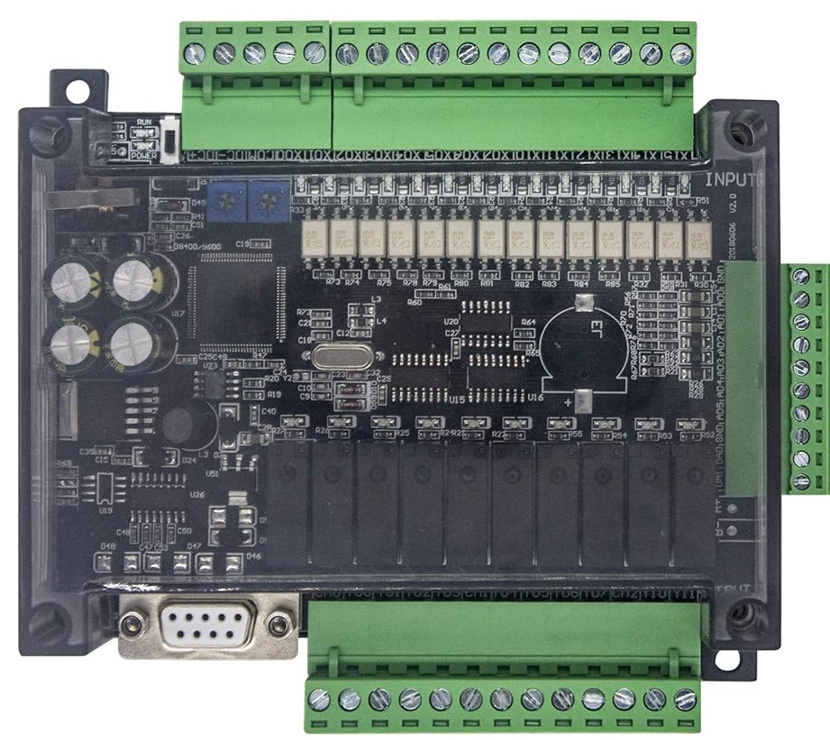
The FX3U-24MR is a programmable logic controller (PLC) manufactured by Mitsubishi Electric. It is part of the FX3U series, which is renowned for its compact design, high performance, and modular expandability. This PLC is equipped with 24 input/output points, making it suitable for a wide range of automation and control applications. The FX3U-24MR is commonly used in industrial automation, manufacturing processes, and building management systems.
Explore Projects Built with fx3u-24mr


Explore Projects Built with fx3u-24mr
Common Applications and Use Cases
- Industrial machinery control
- Conveyor belt automation
- Process monitoring and control
- Building automation systems
- Packaging and assembly line operations
- Integration with Human-Machine Interfaces (HMIs) for advanced control
Technical Specifications
Key Technical Details
| Specification | Value |
|---|---|
| Manufacturer | Mitsubishi Electric |
| Model | FX3U-24MR |
| Power Supply Voltage | 100-240V AC |
| Power Consumption | 20W |
| Number of Inputs | 14 digital inputs |
| Number of Outputs | 10 relay outputs |
| Input Voltage Range | 24V DC |
| Output Type | Relay |
| Communication Ports | RS-422 (built-in), optional modules for Ethernet, RS-485, etc. |
| Programming Language | Ladder Logic (via GX Works2 or GX Developer software) |
| Operating Temperature Range | 0°C to 55°C |
| Dimensions | 90mm x 90mm x 75mm |
| Weight | Approximately 0.5 kg |
Pin Configuration and Descriptions
The FX3U-24MR has 24 I/O points, divided into 14 inputs and 10 outputs. Below is the pin configuration:
Input Terminals
| Pin Number | Description | Voltage Range | Notes |
|---|---|---|---|
| X0 - X13 | Digital Inputs | 24V DC | Used for connecting sensors, switches, etc. |
Output Terminals
| Pin Number | Description | Output Type | Notes |
|---|---|---|---|
| Y0 - Y9 | Relay Outputs | Relay | Used for controlling actuators, motors, etc. |
Power and Communication Terminals
| Pin Number | Description | Notes |
|---|---|---|
| L, N | Power Supply Input | Connect to 100-240V AC |
| RS-422 | Communication Port | For programming and data exchange |
Usage Instructions
How to Use the FX3U-24MR in a Circuit
- Power Connection: Connect the L and N terminals to a 100-240V AC power source. Ensure proper grounding to avoid electrical noise.
- Input Connections: Connect sensors, switches, or other input devices to the X0-X13 terminals. Ensure the input voltage is within the 24V DC range.
- Output Connections: Connect actuators, relays, or other output devices to the Y0-Y9 terminals. Verify the load specifications to avoid overloading the outputs.
- Programming: Use Mitsubishi's GX Works2 or GX Developer software to write and upload ladder logic programs to the PLC via the RS-422 communication port.
- Testing: After wiring and programming, test the system to ensure all inputs and outputs function as expected.
Important Considerations and Best Practices
- Power Supply: Use a stable power source to prevent voltage fluctuations that could damage the PLC.
- Wiring: Keep input and output wiring separate to minimize electrical interference.
- Expandability: The FX3U-24MR supports additional modules for analog I/O, Ethernet communication, and more. Ensure compatibility when adding modules.
- Programming: Always back up your ladder logic programs before making changes.
- Environment: Install the PLC in a clean, dry environment with adequate ventilation to prevent overheating.
Example Code for Basic Input/Output Control
Below is an example of ladder logic code for controlling an output (Y0) based on an input (X0):
// Example Ladder Logic for FX3U-24MR
// This program turns on output Y0 when input X0 is activated.

|----[ X0 ]----( Y0 )----|

// Explanation:
// - [ X0 ]: Represents the input terminal X0.
// - ( Y0 ): Represents the output terminal Y0.
// When X0 is activated (e.g., a switch is pressed), Y0 will turn on.
Troubleshooting and FAQs
Common Issues and Solutions
PLC Does Not Power On
- Cause: Incorrect power supply connection or voltage.
- Solution: Verify the L and N terminals are connected to a 100-240V AC source. Check for loose connections.
Inputs Not Detected
- Cause: Faulty wiring or incorrect input voltage.
- Solution: Ensure the input devices are properly connected to the X0-X13 terminals and the voltage is within the 24V DC range.
Outputs Not Activating
- Cause: Overloaded output or incorrect wiring.
- Solution: Check the load specifications of the connected devices. Ensure the wiring to Y0-Y9 is correct.
Communication Failure
- Cause: Incorrect RS-422 connection or software settings.
- Solution: Verify the RS-422 cable is securely connected. Check the communication settings in GX Works2 or GX Developer.
FAQs
Q1: Can the FX3U-24MR be used with analog inputs/outputs?
A1: Yes, the FX3U-24MR can be expanded with additional analog I/O modules for applications requiring analog signals.
Q2: What software is required to program the FX3U-24MR?
A2: Mitsubishi's GX Works2 or GX Developer software is used for programming the FX3U-24MR.
Q3: Is the FX3U-24MR compatible with Ethernet communication?
A3: The FX3U-24MR does not have built-in Ethernet but can be expanded with an Ethernet communication module.
Q4: What is the maximum number of I/O points supported?
A4: The FX3U-24MR supports 24 I/O points natively but can be expanded with additional modules for more I/O points.
Q5: How do I reset the PLC to factory settings?
A5: Use the programming software to clear the memory or consult the user manual for hardware reset instructions.