How to Use 2N3904 NPN BJT Transistor: Examples, Pinouts, and Specs
2N3904 NPN BJT Transistor Documentation
1. Introduction
The 2N3904 is a general-purpose NPN bipolar junction transistor (BJT) widely used in electronic circuits for switching and amplification purposes. Known for its low power consumption, high-speed performance, and reliability, the 2N3904 is a versatile component suitable for a variety of applications. It is commonly used in signal amplification, low-power switching, and digital logic circuits.
Common Applications:
- Signal amplification in audio and RF circuits
- Low-power switching in digital and analog circuits
- Driving small loads such as LEDs or relays
- Oscillator and timer circuits
- Interfacing with microcontrollers (e.g., Arduino)
The 2N3904 is a cost-effective and readily available transistor, making it a popular choice for both hobbyists and professionals.
2. Technical Specifications
The following table outlines the key technical specifications of the 2N3904 transistor:
| Parameter | Value | Description |
|---|---|---|
| Transistor Type | NPN | Current flows from collector to emitter when base is biased. |
| Maximum Collector-Emitter Voltage (VCEO) | 40V | Maximum voltage between collector and emitter. |
| Maximum Collector-Base Voltage (VCBO) | 60V | Maximum voltage between collector and base. |
| Maximum Emitter-Base Voltage (VEBO) | 6V | Maximum voltage between emitter and base. |
| Maximum Collector Current (IC) | 200mA | Maximum current through the collector. |
| Power Dissipation (PD) | 625mW | Maximum power the transistor can dissipate. |
| DC Current Gain (hFE) | 30–300 | Amplification factor (varies with current). |
| Transition Frequency (fT) | 300MHz | Maximum frequency for small-signal operation. |
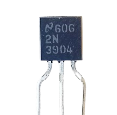
| Package Type | TO-92 | Standard through-hole package. |
Pin Configuration
The 2N3904 transistor comes in a TO-92 package with three pins. The pinout is as follows:
| Pin Number | Pin Name | Description |
|---|---|---|
| 1 | Emitter (E) | Current flows out of the transistor. |
| 2 | Base (B) | Controls the transistor's operation. |
| 3 | Collector (C) | Current flows into the transistor. |
The pinout for the TO-92 package is shown below (flat side facing you):
   _______
  |       |
  |       |
  |_______|
   | | |
   E B C
3. Usage Instructions
How to Use the 2N3904 in a Circuit
The 2N3904 transistor operates as a current-controlled device. A small current applied to the Base (B) controls a larger current flowing between the Collector (C) and Emitter (E). Below are the steps to use the 2N3904 in a circuit:
Determine the Operating Mode:
- Switching Mode: Use the transistor as an on/off switch by saturating or cutting off the base current.
- Amplification Mode: Use the transistor to amplify small input signals.
Connect the Pins:
- Connect the Emitter (E) to ground or the negative terminal of the power supply.
- Connect the Collector (C) to the load (e.g., an LED or motor) and then to the positive terminal of the power supply.
- Apply a small current to the Base (B) through a resistor to control the transistor.
Choose a Base Resistor:
- Use a resistor to limit the base current. The value can be calculated using Ohm's Law:
[
R_B = \frac{V_{in} - V_{BE}}{I_B}
]
Where:
- ( V_{in} ) = Input voltage to the base
- ( V_{BE} ) = Base-emitter voltage (typically 0.7V for the 2N3904)
- ( I_B ) = Desired base current (usually ( I_B = I_C / h_{FE} ))
- Use a resistor to limit the base current. The value can be calculated using Ohm's Law:
[
R_B = \frac{V_{in} - V_{BE}}{I_B}
]
Where:
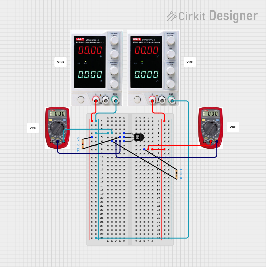
Test the Circuit:
- Verify the transistor's operation by measuring the voltage and current at each pin.
Example Circuit: Switching an LED
Below is an example of using the 2N3904 to switch an LED on and off:
 +5V ----> LED ----> 330Ω Resistor ----> Collector (C)
                     |
                     |
                   Emitter (E) ----> GND
                     |
                     |
 Base (B) ----> 10kΩ Resistor ----> Digital Pin (e.g., Arduino)
4. Arduino Example Code
The following code demonstrates how to use the 2N3904 transistor to control an LED with an Arduino UNO:
// Define the pin connected to the transistor's base
const int transistorBasePin = 9; // Digital pin 9

void setup() {
  pinMode(transistorBasePin, OUTPUT); // Set the pin as an output
}

void loop() {
  digitalWrite(transistorBasePin, HIGH); // Turn on the transistor (LED ON)
  delay(1000); // Wait for 1 second
  digitalWrite(transistorBasePin, LOW);  // Turn off the transistor (LED OFF)
  delay(1000); // Wait for 1 second
}
Notes:
- Use a 10kΩ resistor between the Arduino pin and the transistor's base to limit the base current.
- Ensure the LED has a current-limiting resistor (e.g., 330Ω) to prevent damage.
5. Troubleshooting and FAQs
Common Issues and Solutions
| Issue | Possible Cause | Solution |
|---|---|---|
| Transistor does not turn on | Insufficient base current | Check the base resistor value and input voltage. |
| Transistor overheats | Exceeding power dissipation limit | Reduce the load current or use a heatsink. |
| LED does not light up | Incorrect pin connections | Verify the pinout and connections. |
| Circuit behaves erratically | Noise or unstable input signal | Add a decoupling capacitor near the transistor. |
FAQs
What is the maximum current the 2N3904 can handle?
- The maximum collector current is 200mA. Exceeding this limit may damage the transistor.
Can the 2N3904 be used for high-power applications?
- No, the 2N3904 is designed for low-power applications. For high-power circuits, consider using a power transistor like the TIP120.
What is the typical base-emitter voltage (VBE)?
- The typical base-emitter voltage is 0.7V when the transistor is conducting.
Can the 2N3904 be used with an Arduino?
- Yes, the 2N3904 is commonly used with microcontrollers like the Arduino for switching and amplification tasks.
6. Conclusion
The 2N3904 NPN BJT transistor is a versatile and reliable component for low-power switching and amplification applications. Its ease of use, availability, and compatibility with microcontrollers like Arduino make it an essential part of any electronics enthusiast's toolkit. By following the guidelines and best practices outlined in this documentation, you can effectively integrate the 2N3904 into your projects.
Explore Projects Built with 2N3904 NPN BJT Transistor

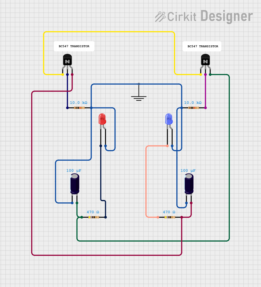

Explore Projects Built with 2N3904 NPN BJT Transistor