How to Use Adafruit Si5351A Clock Generator: Examples, Pinouts, and Specs
Introduction
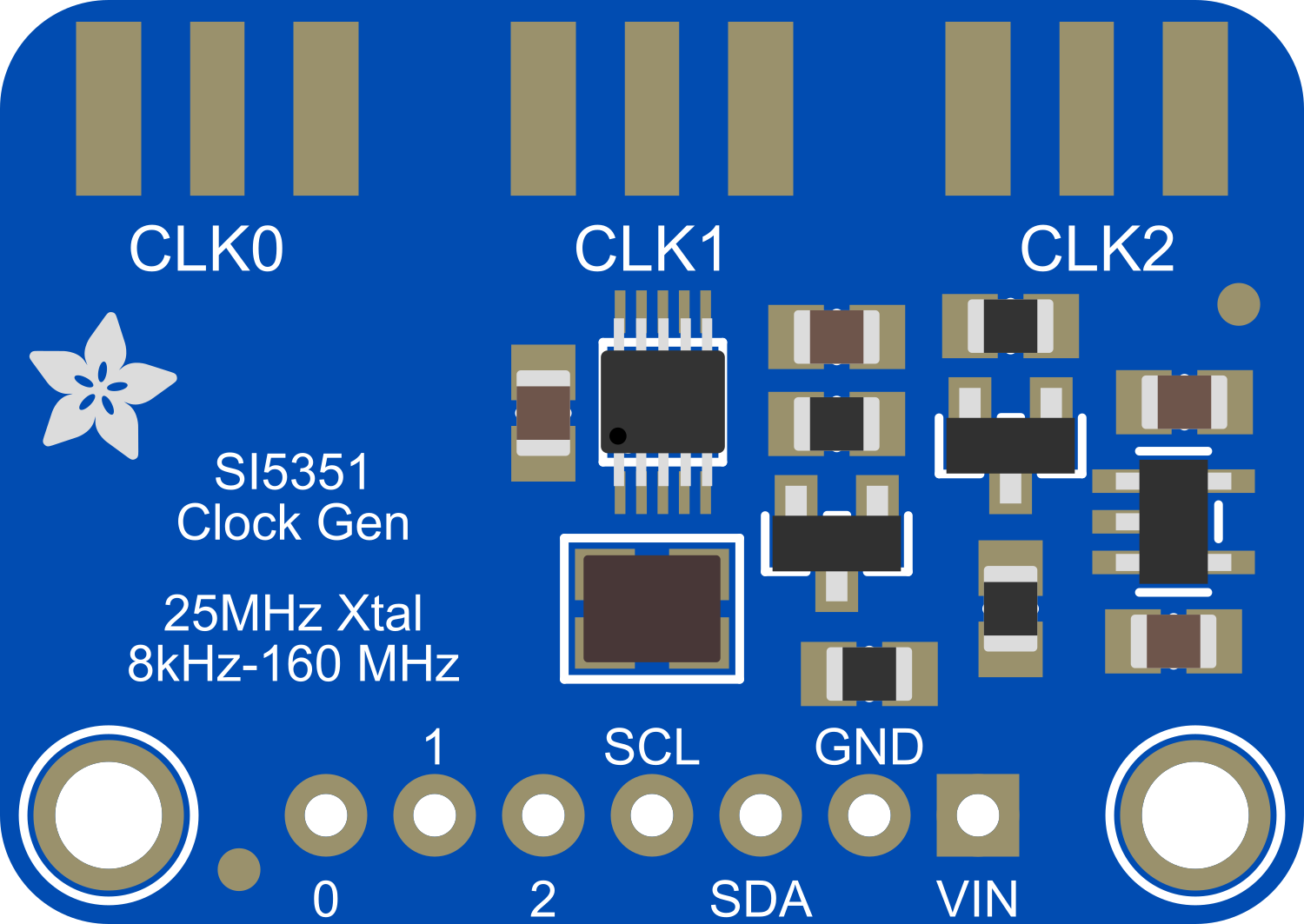
The Adafruit Si5351A Clock Generator is a highly versatile and programmable clock generator module based on the Silicon Labs Si5351A chip. It is capable of generating multiple independent clock signals over a wide frequency range from 2.5 kHz to 200 MHz. This component is particularly useful in applications requiring precise timing and frequency generation, such as in radio transceivers, digital audio devices, and microcontroller projects.
Explore Projects Built with Adafruit Si5351A Clock Generator

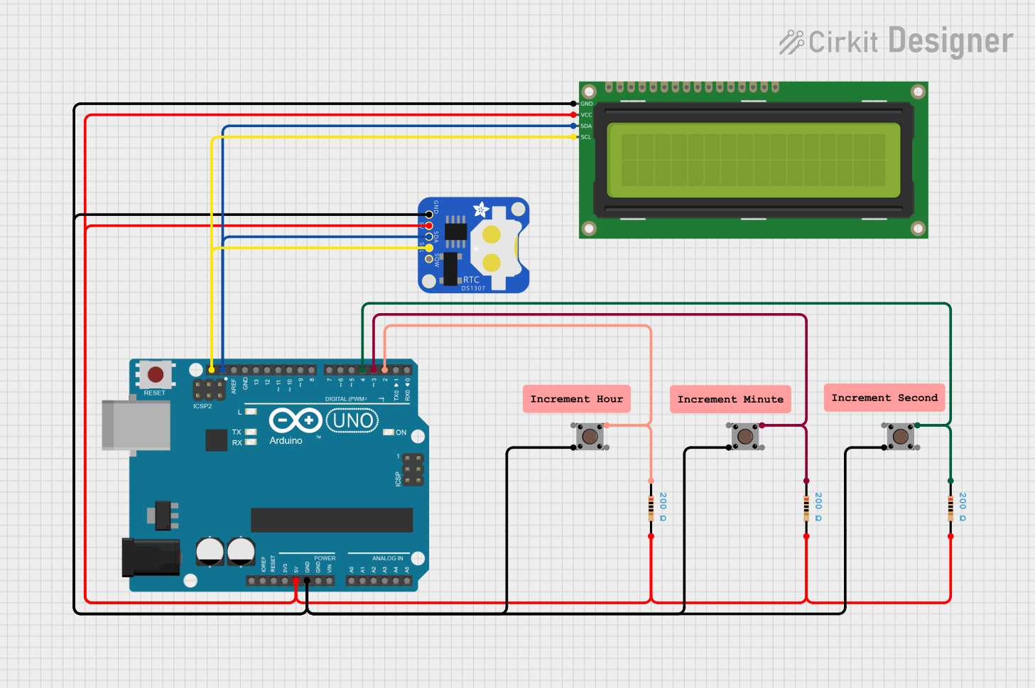
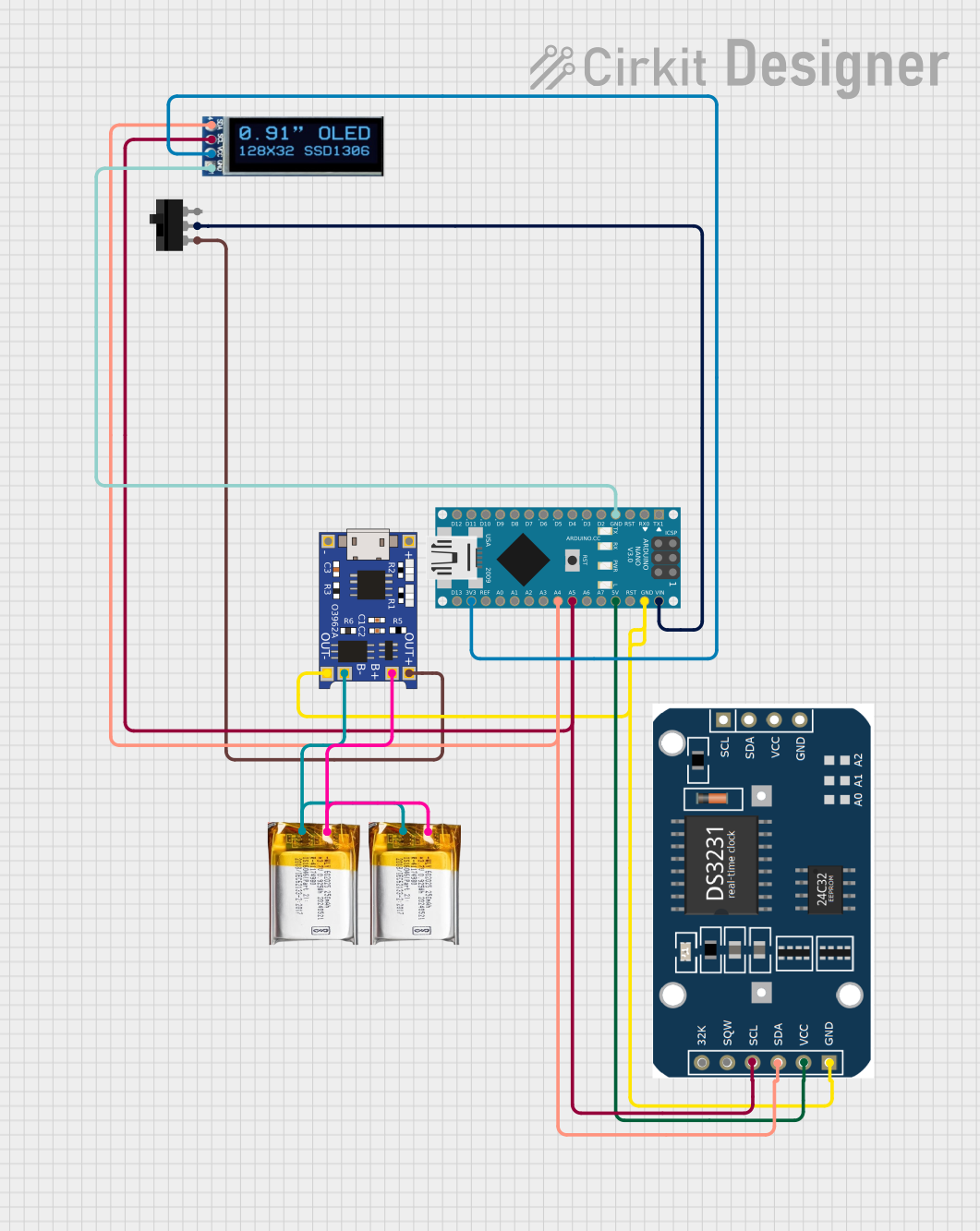
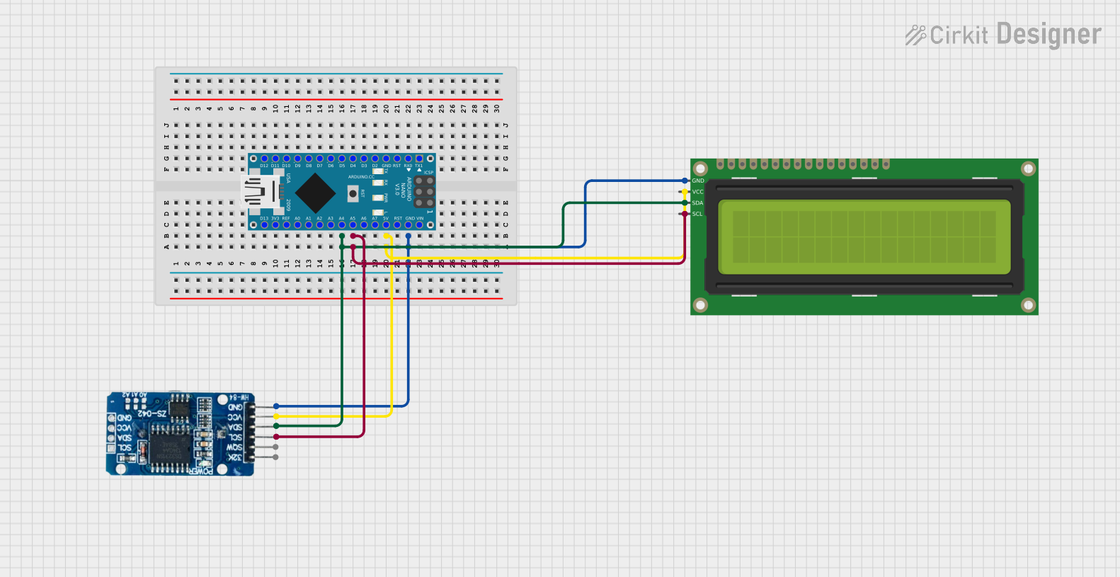
Explore Projects Built with Adafruit Si5351A Clock Generator
Common Applications and Use Cases
- Amateur radio and RF communications
- Digital audio synthesis and processing
- Microcontroller clock source
- Precision timing for embedded systems
- Signal generation for testing and development
Technical Specifications
Key Technical Details
- Frequency Range: 2.5 kHz to 200 MHz
- Voltage Supply: 3.3V to 5V
- Output Drive Strength: Configurable (2mA to 8mA)
- Number of Outputs: 3 (independent and programmable)
- Frequency Stability: ±50 ppm
- Interface: I2C
Pin Configuration and Descriptions
| Pin Number | Name | Description |
|---|---|---|
| 1 | GND | Ground connection |
| 2 | VCC | Power supply (3.3V to 5V) |
| 3 | SCL | I2C clock line |
| 4 | SDA | I2C data line |
| 5 | 0 | Clock output 0 |
| 6 | 1 | Clock output 1 |
| 7 | 2 | Clock output 2 |
| 8 | OE | Output enable (active low) |
| 9 | RST | Reset pin (active low) |
Usage Instructions
How to Use the Component in a Circuit
- Power Supply: Connect the VCC pin to a 3.3V or 5V power source and the GND pin to the ground.
- I2C Communication: Connect the SCL and SDA pins to the corresponding I2C clock and data lines on your microcontroller.
- Output Enable: Optionally, connect the OE pin to a digital output on your microcontroller if you wish to control the enable state of the outputs programmatically.
- Reset: Optionally, connect the RST pin to a digital output on your microcontroller to reset the Si5351A chip when required.
- Clock Outputs: Connect the 0, 1, and 2 pins to the inputs of devices that require clock signals.
Important Considerations and Best Practices
- Ensure that the power supply voltage is within the specified range to prevent damage to the Si5351A chip.
- Use pull-up resistors on the I2C lines if they are not already present on the microcontroller board.
- Keep the clock signal traces as short as possible to minimize signal degradation.
- Avoid running clock signal traces parallel to high-speed data lines to prevent interference.
Example Connection to an Arduino UNO
// Include the required libraries
#include <Wire.h>
#include <Adafruit_Si5351.h>

// Create an instance of the Si5351 object
Adafruit_Si5351 clockgen = Adafruit_Si5351();

void setup() {
  // Start the I2C communication
  Wire.begin();

  // Begin communication with the Si5351A chip
  if (!clockgen.begin()) {
    Serial.println("Si5351A not found");
    while (1);
  }

  // Setup the clock generator (e.g., 10 MHz on Clock output 0)
  clockgen.setupPLL(SI5351_PLL_A, 40, 1, 900);
  clockgen.setupMultisynth(0, SI5351_PLL_A, 40, 1, 1);
  clockgen.enableOutput(0, true);
}

void loop() {
  // Your main code goes here
}
Troubleshooting and FAQs
Common Issues Users Might Face
- No Output Signal: Ensure that the power supply is connected correctly and the I2C communication is established.
- Incorrect Frequency: Double-check the PLL and multisynth configuration parameters.
- Signal Distortion: Keep the output traces short and consider impedance matching if necessary.
Solutions and Tips for Troubleshooting
- Verify connections and solder joints for any loose or cold solder points.
- Use an oscilloscope to check the output signals for expected frequency and waveform.
- Ensure that the OE pin is not held low unintentionally, as this will disable the outputs.
FAQs
Q: Can I generate different frequencies on each output? A: Yes, each output can be independently programmed to generate different frequencies.
Q: What is the maximum output frequency the Si5351A can generate? A: The Si5351A can generate frequencies up to 200 MHz.
Q: Is it possible to use the Si5351A with a 5V microcontroller? A: Yes, the Si5351A can be powered with 5V and is 5V-tolerant on the I2C lines.
Q: How do I change the frequency of an output after the initial setup? A: You can reconfigure the PLL and multisynth settings for the desired output using the library functions provided.
This documentation provides a comprehensive guide to using the Adafruit Si5351A Clock Generator. For more detailed information, refer to the datasheet and the Adafruit Si5351 library documentation.