How to Use Spark Max Engine Controller: Examples, Pinouts, and Specs
Introduction
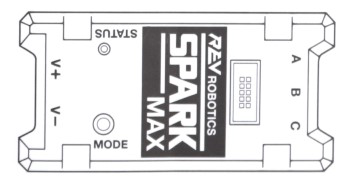
The Spark Max Engine Controller is a high-performance motor controller specifically designed for brushless DC (BLDC) motors. It features advanced control algorithms, built-in encoder support, and compatibility with multiple communication protocols, making it a versatile and powerful choice for robotics, industrial automation, and other motor control applications.
Explore Projects Built with Spark Max Engine Controller
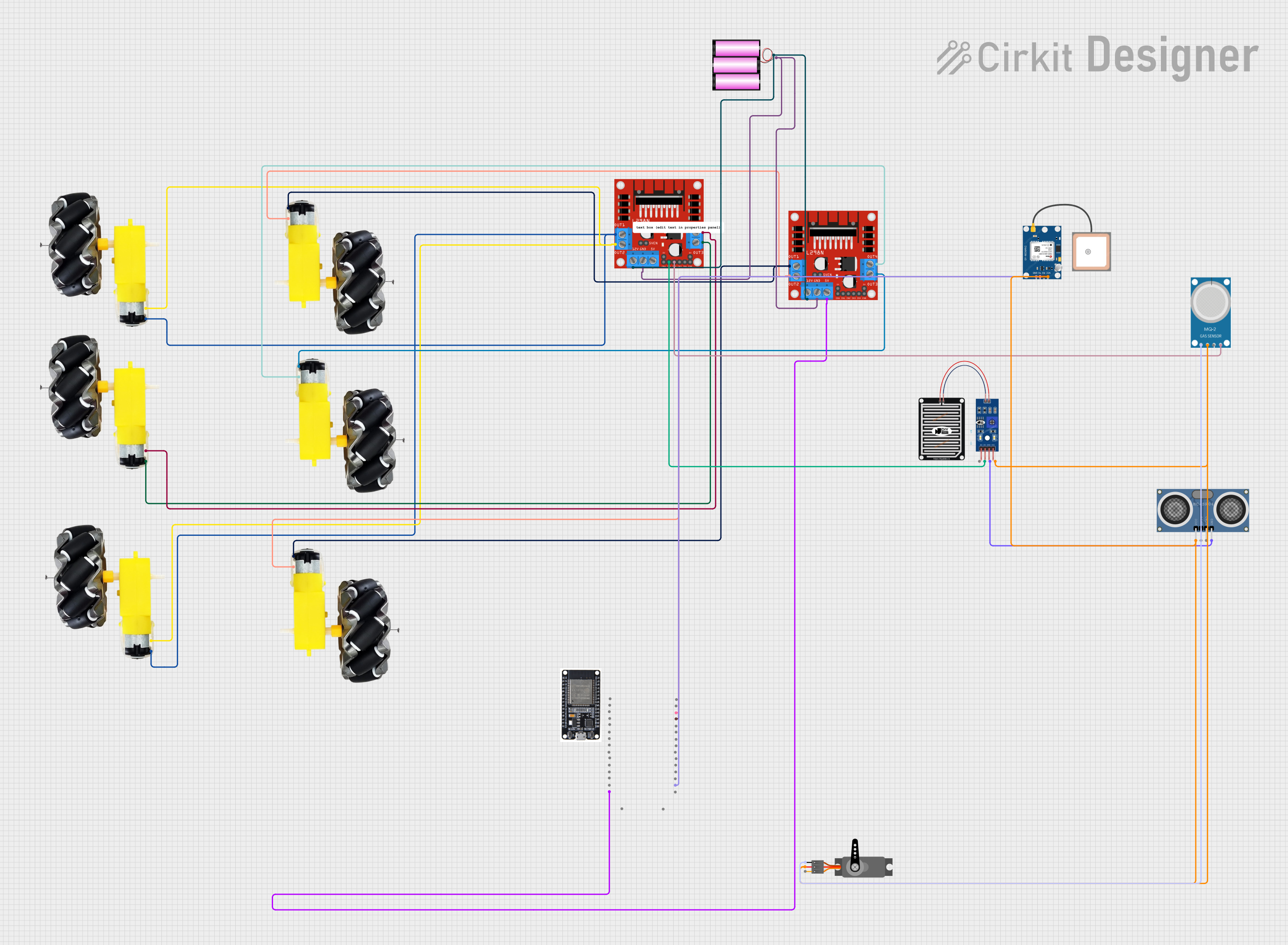

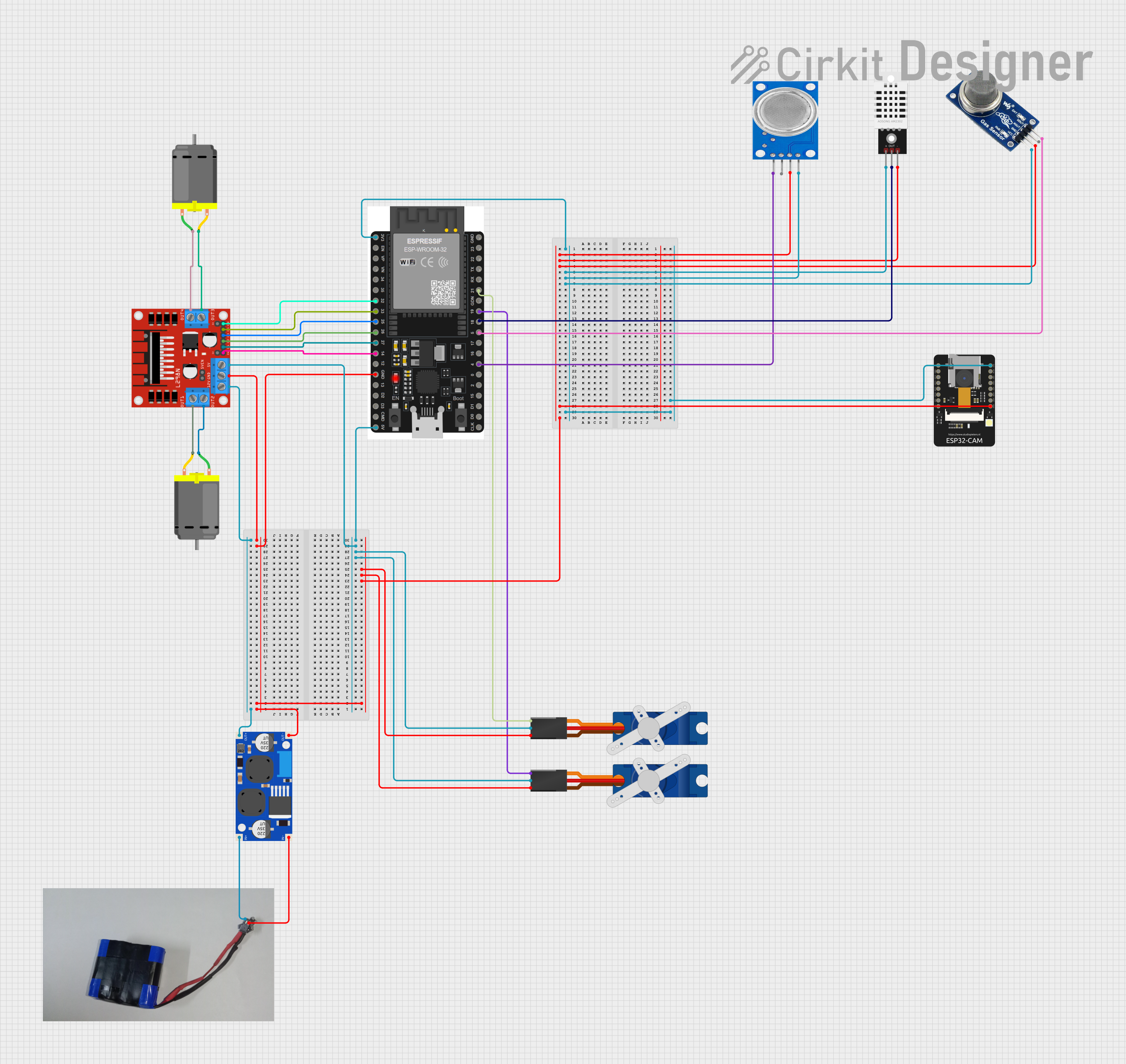
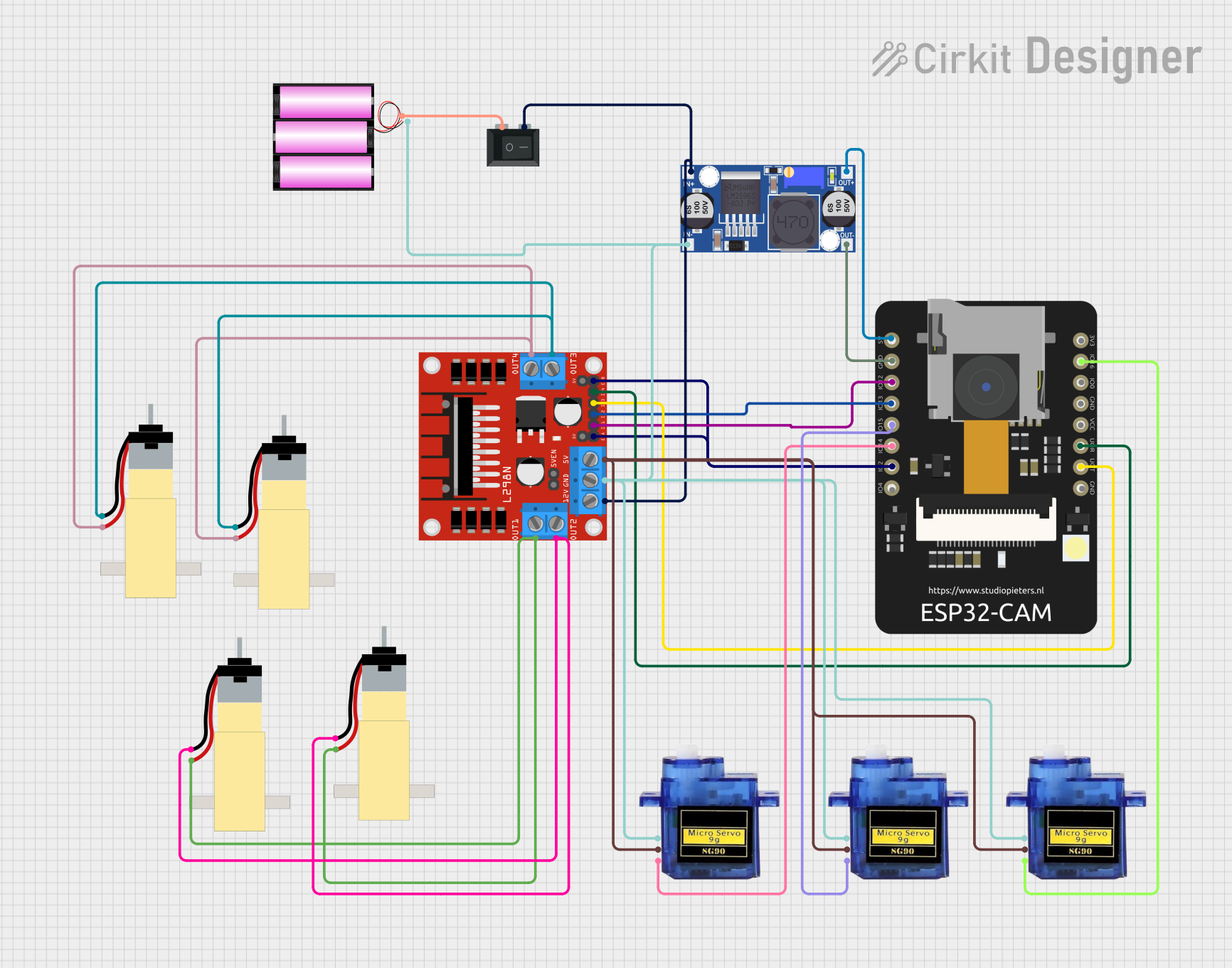
Explore Projects Built with Spark Max Engine Controller
Common Applications and Use Cases
- Robotics: Precise motor control for autonomous and teleoperated systems.
- Industrial Automation: Driving BLDC motors in conveyor belts, robotic arms, and machinery.
- Electric Vehicles: Efficient motor control for small electric vehicles and drones.
- Research and Development: Prototyping and testing advanced motor control systems.
Technical Specifications
The Spark Max Engine Controller is engineered to deliver reliable and efficient performance. Below are its key technical specifications:
General Specifications
| Parameter | Value |
|---|---|
| Input Voltage Range | 5.5V to 24V |
| Continuous Current | 40A |
| Peak Current | 100A (for 2 seconds) |
| Motor Compatibility | Brushless DC (BLDC) motors |
| Communication Protocols | CAN, PWM, USB-C, Analog Input |
| Encoder Support | Quadrature, Hall Effect |
| Dimensions | 90mm x 45mm x 20mm |
| Weight | 100g |
Pin Configuration and Descriptions
The Spark Max Engine Controller features a variety of input and output pins for flexible integration. Below is the pinout description:
Power and Motor Connections
| Pin Name | Description |
|---|---|
| VIN+ | Positive input voltage (5.5V to 24V). |
| VIN- | Ground connection for input voltage. |
| M+ | Positive terminal for motor connection. |
| M- | Negative terminal for motor connection. |
Control and Communication Pins
| Pin Name | Description |
|---|---|
| CANH | CAN bus high signal for communication. |
| CANL | CAN bus low signal for communication. |
| PWM | PWM input for motor speed control. |
| USB-C | USB-C port for configuration and updates. |
| ENC_A | Encoder channel A input. |
| ENC_B | Encoder channel B input. |
| ENC_I | Encoder index signal input. |
| ANALOG | Analog input for speed control. |
Usage Instructions
The Spark Max Engine Controller is designed for ease of use while offering advanced features for experienced users. Follow the steps below to integrate it into your project:
Basic Setup
- Power Connection: Connect the VIN+ and VIN- pins to a power source within the 5.5V to 24V range.
- Motor Connection: Attach the motor leads to the M+ and M- terminals, ensuring correct polarity.
- Control Signal: Choose a control method (e.g., PWM, CAN, or Analog) and connect the appropriate pins.
- Encoder Connection (Optional): If using an encoder, connect the encoder's A, B, and I signals to the ENC_A, ENC_B, and ENC_I pins, respectively.
Important Considerations
- Ensure the input voltage does not exceed 24V to avoid damaging the controller.
- Use appropriate wire gauges for power and motor connections to handle the current load.
- Securely mount the controller to prevent vibration or movement during operation.
- If using CAN communication, terminate the CAN bus with a 120-ohm resistor at both ends.
Example: Using Spark Max with Arduino UNO
The Spark Max Engine Controller can be controlled via PWM signals from an Arduino UNO. Below is an example code snippet to control motor speed:
// Include necessary libraries
#include <Servo.h> // Library to generate PWM signals

// Define the PWM pin connected to the Spark Max
const int pwmPin = 9;

// Create a Servo object to generate PWM
Servo motorController;

void setup() {
  // Attach the PWM pin to the Servo object
  motorController.attach(pwmPin);

  // Set initial motor speed to 0 (stopped)
  motorController.writeMicroseconds(1500);
  // 1500 µs is typically the neutral signal for motor controllers
}

void loop() {
  // Example: Gradually increase motor speed
  for (int speed = 1500; speed <= 2000; speed += 10) {
    motorController.writeMicroseconds(speed); // Send PWM signal
    delay(100); // Wait for 100 ms
  }

  // Example: Gradually decrease motor speed
  for (int speed = 2000; speed >= 1500; speed -= 10) {
    motorController.writeMicroseconds(speed); // Send PWM signal
    delay(100); // Wait for 100 ms
  }
}
Best Practices
- Calibrate the motor controller using the manufacturer's software before use.
- Use proper heat dissipation methods, such as a heatsink or fan, for high-current applications.
- Regularly inspect connections to ensure they are secure and free of corrosion.
Troubleshooting and FAQs
Common Issues and Solutions
Motor Not Spinning
- Cause: Incorrect wiring or insufficient power supply.
- Solution: Verify all connections and ensure the power supply meets the voltage and current requirements.
Overheating
- Cause: Prolonged operation at high current or inadequate cooling.
- Solution: Add a heatsink or fan to improve heat dissipation.
Erratic Motor Behavior
- Cause: Noise in the control signal or incorrect encoder wiring.
- Solution: Use shielded cables for control signals and double-check encoder connections.
No Communication via CAN
- Cause: Missing or incorrect termination resistors.
- Solution: Ensure 120-ohm resistors are installed at both ends of the CAN bus.
FAQs
Q: Can the Spark Max be used with brushed DC motors?
A: No, the Spark Max is specifically designed for brushless DC motors.
Q: How do I update the firmware?
A: Connect the controller to a computer via the USB-C port and use the manufacturer's configuration software to update the firmware.
Q: What is the default PWM frequency for the Spark Max?
A: The Spark Max operates with a default PWM frequency of 1 kHz.
Q: Can I use the Spark Max with a Raspberry Pi?
A: Yes, the Spark Max can be controlled via PWM or CAN communication from a Raspberry Pi.
By following this documentation, you can effectively integrate and operate the Spark Max Engine Controller in your projects.