How to Use XM125: Examples, Pinouts, and Specs
Introduction
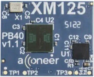
The XM125, manufactured by Acconner (Part ID: PB40 v1.1), is a high-performance, low-noise operational amplifier designed for precision signal processing applications. With its wide bandwidth and low distortion, the XM125 is ideal for applications requiring high accuracy and stability. It is commonly used in audio systems, instrumentation circuits, and other precision analog signal processing tasks.
Explore Projects Built with XM125


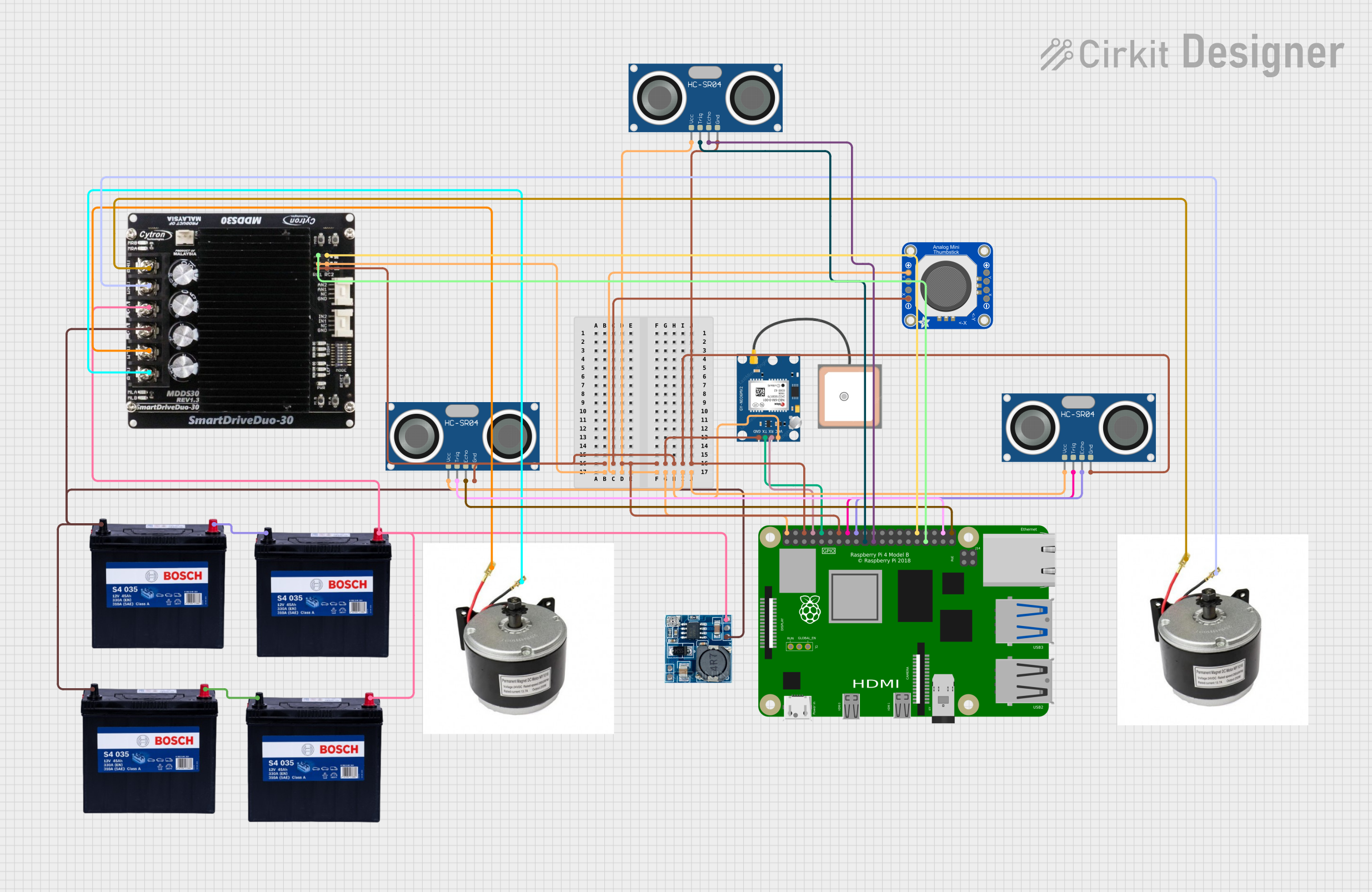
Explore Projects Built with XM125
Common Applications
- Audio preamplifiers and equalizers
- Instrumentation amplifiers
- Active filters and integrators
- Data acquisition systems
- Precision voltage followers
Technical Specifications
Key Technical Details
| Parameter | Value |
|---|---|
| Supply Voltage Range | ±2.5V to ±18V |
| Input Offset Voltage | 0.5 mV (typical) |
| Input Bias Current | 10 nA (typical) |
| Gain Bandwidth Product | 10 MHz |
| Slew Rate | 5 V/µs |
| Output Voltage Swing | ±(Vcc - 1.5V) |
| Total Harmonic Distortion | 0.0003% (typical) |
| Operating Temperature | -40°C to +85°C |
| Package Type | 8-pin DIP or SOIC |
Pin Configuration and Descriptions
The XM125 is available in an 8-pin package. The pinout and descriptions are as follows:
| Pin Number | Name | Description |
|---|---|---|
| 1 | Offset Null | Used for offset voltage adjustment (optional) |
| 2 | Inverting Input (-) | Inverting input terminal for the op-amp |
| 3 | Non-Inverting Input (+) | Non-inverting input terminal |
| 4 | V- (GND) | Negative power supply or ground |
| 5 | Offset Null | Used for offset voltage adjustment (optional) |
| 6 | Output | Output terminal of the op-amp |
| 7 | V+ | Positive power supply |
| 8 | NC (No Connect) | Not connected internally |
Usage Instructions
How to Use the XM125 in a Circuit
- Power Supply: Connect the XM125 to a dual power supply (e.g., ±12V) or a single supply (e.g., 5V and GND) depending on your application. Ensure the supply voltage is within the specified range (±2.5V to ±18V).
- Input Connections: Connect the signal source to the inverting (-) or non-inverting (+) input, depending on the desired configuration (e.g., inverting or non-inverting amplifier).
- Output Load: Ensure the load connected to the output does not exceed the op-amp's drive capability. For best performance, use a load impedance of at least 10 kΩ.
- Offset Adjustment: If precise offset voltage adjustment is required, connect a 10 kΩ potentiometer between the two offset null pins (Pins 1 and 5) and tie the wiper to V+.
- Bypass Capacitors: Place decoupling capacitors (e.g., 0.1 µF ceramic and 10 µF electrolytic) close to the power supply pins to reduce noise and improve stability.
Example Circuit: Non-Inverting Amplifier
Below is an example of using the XM125 as a non-inverting amplifier with a gain of 11.
/* Example: Non-Inverting Amplifier Circuit
   Gain = 1 + (R2 / R1)
   R1 = 10 kΩ, R2 = 100 kΩ, Gain = 11
*/

#include <Arduino.h>

// No specific code is required for the XM125 itself, as it is an analog component.
// However, you can use the Arduino's ADC to read the amplified signal.

void setup() {
  Serial.begin(9600); // Initialize serial communication
  analogReference(DEFAULT); // Use default reference voltage (5V for Arduino UNO)
}

void loop() {
  int sensorValue = analogRead(A0); // Read the amplified signal from pin A0
  float voltage = sensorValue * (5.0 / 1023.0); // Convert ADC value to voltage
  Serial.print("Amplified Voltage: ");
  Serial.println(voltage); // Print the voltage to the serial monitor
  delay(500); // Wait for 500 ms
}
Important Considerations
- Stability: To avoid oscillations, ensure proper feedback network design and use bypass capacitors near the power supply pins.
- Input Impedance: The XM125 has a high input impedance, but ensure the source impedance is low enough to avoid signal attenuation.
- Thermal Management: Operate the XM125 within the specified temperature range (-40°C to +85°C) to ensure reliable performance.
Troubleshooting and FAQs
Common Issues and Solutions
No Output Signal
- Cause: Incorrect power supply connections.
- Solution: Verify the power supply polarity and voltage levels.
Output Signal Distortion
- Cause: Exceeding the output voltage swing or driving a low-impedance load.
- Solution: Ensure the load impedance is at least 10 kΩ and the input signal is within the op-amp's linear range.
Oscillations or Noise
- Cause: Insufficient bypassing or improper feedback network design.
- Solution: Add decoupling capacitors (0.1 µF and 10 µF) near the power supply pins and review the feedback network.
High Offset Voltage
- Cause: Unadjusted offset null pins.
- Solution: Use a 10 kΩ potentiometer between Pins 1 and 5 to fine-tune the offset voltage.
FAQs
Q: Can the XM125 operate with a single power supply?
A: Yes, the XM125 can operate with a single supply (e.g., 5V and GND). However, ensure the input signal and output swing remain within the op-amp's operating range.
Q: What is the maximum gain I can achieve with the XM125?
A: The maximum gain depends on the feedback network and the op-amp's bandwidth. For high gains, ensure the gain-bandwidth product (10 MHz) is not exceeded.
Q: Is the XM125 suitable for audio applications?
A: Yes, the XM125's low noise and low distortion make it an excellent choice for audio preamplifiers and equalizers.
Q: How do I protect the XM125 from damage?
A: Use proper decoupling capacitors, avoid exceeding the supply voltage range, and ensure the input signals do not exceed the supply rails.
This concludes the documentation for the XM125 operational amplifier. For further assistance, refer to the manufacturer's datasheet or contact Acconner support.