How to Use RECORD PLAYBACK IC: Examples, Pinouts, and Specs
Introduction
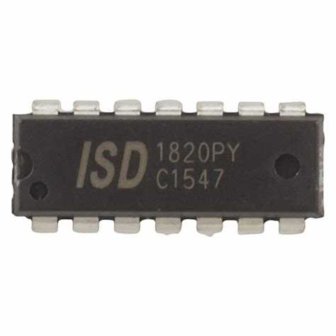
The Record Playback IC is a specialized integrated circuit designed to facilitate the recording and playback of audio signals. It is commonly used in audio devices such as tape recorders, digital audio players, voice recorders, and other audio storage and retrieval systems. This IC simplifies the process of capturing audio input, storing it in memory, and playing it back with minimal external components.
Explore Projects Built with RECORD PLAYBACK IC
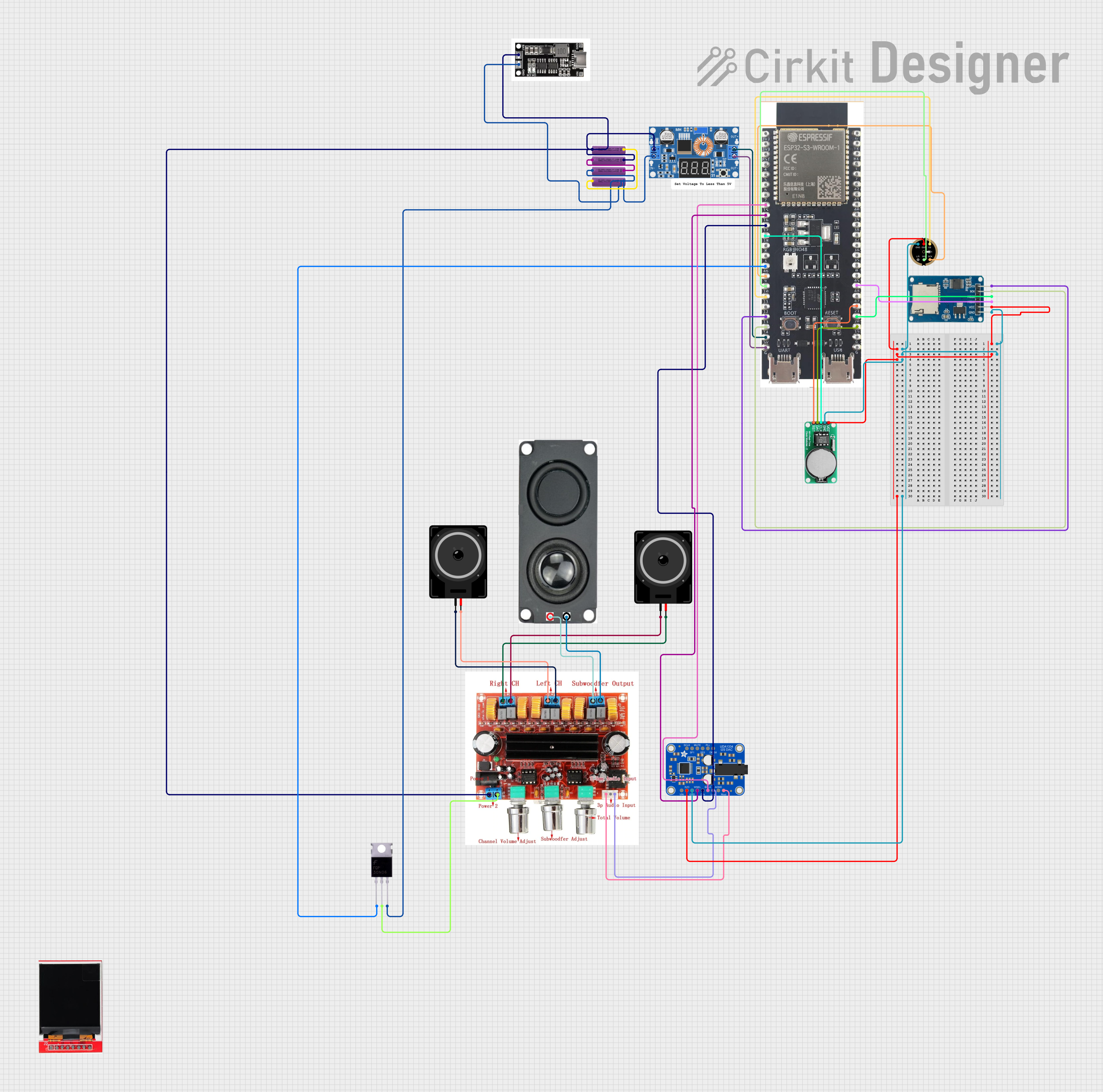
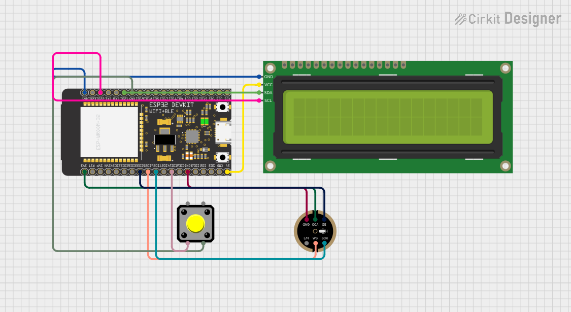
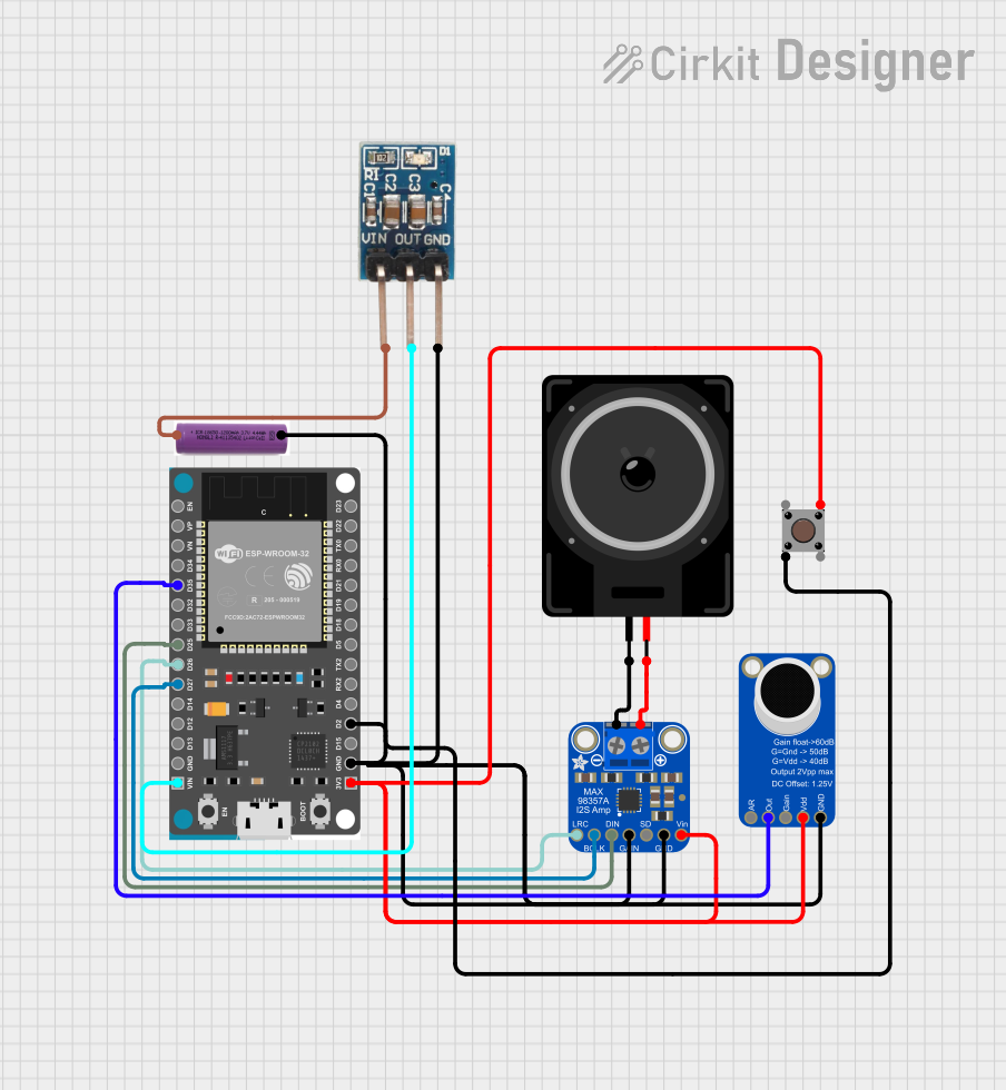
Explore Projects Built with RECORD PLAYBACK IC
Common Applications and Use Cases
- Voice recorders and memo devices
- Audio greeting cards
- Toys and novelty items with sound playback
- Digital answering machines
- Audio storage systems in embedded devices
Technical Specifications
Below are the general technical specifications for a typical Record Playback IC. Note that specific values may vary depending on the manufacturer and model.
| Parameter | Value |
|---|---|
| Operating Voltage | 2.4V to 5.5V |
| Operating Current | 25mA (typical during playback) |
| Audio Storage Duration | 10 seconds to 120 seconds (model-dependent) |
| Sampling Rate | 4kHz to 12kHz |
| Output Type | Speaker driver or line-out |
| Input Type | Microphone or line-in |
| Memory Type | Non-volatile (e.g., Flash or EEPROM) |
| Package Type | DIP, SOP, or QFN |
Pin Configuration and Descriptions
Below is a typical pinout for a Record Playback IC. The exact pin configuration may vary depending on the specific IC model.
| Pin Number | Pin Name | Description |
|---|---|---|
| 1 | VCC | Power supply (2.4V to 5.5V) |
| 2 | GND | Ground |
| 3 | MIC_IN | Microphone input for recording |
| 4 | SPK_OUT+ | Positive terminal for speaker output |
| 5 | SPK_OUT- | Negative terminal for speaker output |
| 6 | PLAY | Trigger pin for playback mode |
| 7 | REC | Trigger pin for recording mode |
| 8 | OSC_RES | Oscillator resistor pin for setting sampling rate |
Usage Instructions
How to Use the Component in a Circuit
- Power Supply: Connect the VCC pin to a stable power source (2.4V to 5.5V) and the GND pin to ground.
- Audio Input: Connect a microphone or line-in source to the MIC_IN pin. Use a coupling capacitor if required by the IC's datasheet.
- Audio Output: Connect a speaker or audio amplifier to the SPK_OUT+ and SPK_OUT- pins. Ensure the speaker impedance matches the IC's specifications.
- Control Pins: Use push buttons or microcontroller GPIOs to control the PLAY and REC pins. Pull-up or pull-down resistors may be required.
- Oscillator Resistor: Connect a resistor to the OSC_RES pin to set the desired sampling rate. Refer to the datasheet for recommended resistor values.
Important Considerations and Best Practices
- Decoupling Capacitors: Place a 0.1µF ceramic capacitor close to the VCC pin to filter noise.
- Speaker Impedance: Ensure the speaker impedance matches the IC's output specifications to avoid distortion or damage.
- Memory Duration: Choose an IC with sufficient memory duration for your application (e.g., 10 seconds for short messages, 120 seconds for longer recordings).
- Microphone Sensitivity: Use a microphone with appropriate sensitivity and impedance for optimal recording quality.
- Avoid Overdriving: Do not exceed the maximum voltage or current ratings to prevent damage to the IC.
Example: Connecting to an Arduino UNO
The Record Playback IC can be controlled using an Arduino UNO. Below is an example code snippet to trigger recording and playback using digital pins.
// Define pin connections for the Record Playback IC
const int playPin = 7;  // Pin connected to the PLAY pin of the IC
const int recPin = 8;   // Pin connected to the REC pin of the IC

void setup() {
  // Set control pins as outputs
  pinMode(playPin, OUTPUT);
  pinMode(recPin, OUTPUT);

  // Initialize pins to LOW
  digitalWrite(playPin, LOW);
  digitalWrite(recPin, LOW);
}

void loop() {
  // Example: Trigger recording for 5 seconds
  digitalWrite(recPin, HIGH);  // Start recording
  delay(5000);                 // Record for 5 seconds
  digitalWrite(recPin, LOW);   // Stop recording

  delay(2000);                 // Wait for 2 seconds

  // Example: Trigger playback
  digitalWrite(playPin, HIGH); // Start playback
  delay(1000);                 // Allow playback to start
  digitalWrite(playPin, LOW);  // Stop playback trigger

  delay(5000);                 // Wait before repeating
}
Troubleshooting and FAQs
Common Issues and Solutions
No Audio Output
- Cause: Incorrect speaker connection or impedance mismatch.
- Solution: Verify the speaker connections and ensure the impedance matches the IC's specifications.
Distorted Playback
- Cause: Overdriven input signal or incorrect sampling rate.
- Solution: Reduce the input signal amplitude and check the oscillator resistor value.
Recording Not Working
- Cause: Faulty microphone or incorrect MIC_IN connection.
- Solution: Test the microphone separately and ensure proper coupling to the MIC_IN pin.
Playback Stops Abruptly
- Cause: Insufficient memory duration for the recording.
- Solution: Use an IC with a longer recording duration or reduce the recording length.
FAQs
Q: Can I use a line-in source instead of a microphone?
A: Yes, but ensure the input signal is within the IC's acceptable voltage range.Q: How do I increase the recording duration?
A: Choose an IC with a larger memory capacity or reduce the sampling rate (if adjustable).Q: Can I connect the IC directly to a microcontroller?
A: Yes, the control pins (PLAY and REC) can be triggered using GPIO pins of a microcontroller.Q: What type of speaker should I use?
A: Use a speaker with the impedance and power rating specified in the IC's datasheet, typically 8Ω.
This documentation provides a comprehensive guide to understanding and using a Record Playback IC effectively. For specific details, always refer to the datasheet of the IC model you are using.