
How to Use M5450 LED Driver: Examples, Pinouts, and Specs

 Design with M5450 LED Driver in Cirkit Designer
Introduction
The M5450 LED Driver, manufactured by STMicroelectronics, is a versatile and efficient LED driver designed to control the brightness of LED lights using Pulse Width Modulation (PWM). It is capable of driving up to 35 LEDs in series or parallel configurations, making it ideal for applications requiring precise brightness control and low thermal dissipation.
Explore Projects Built with M5450 LED Driver
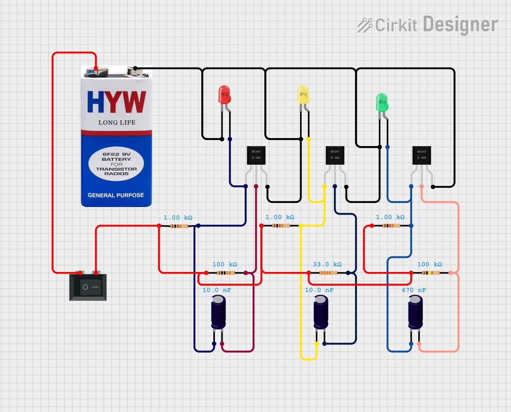 Open Project in Cirkit Designer
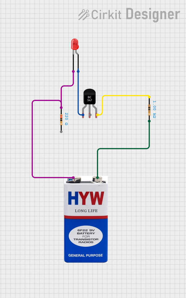 Open Project in Cirkit Designer
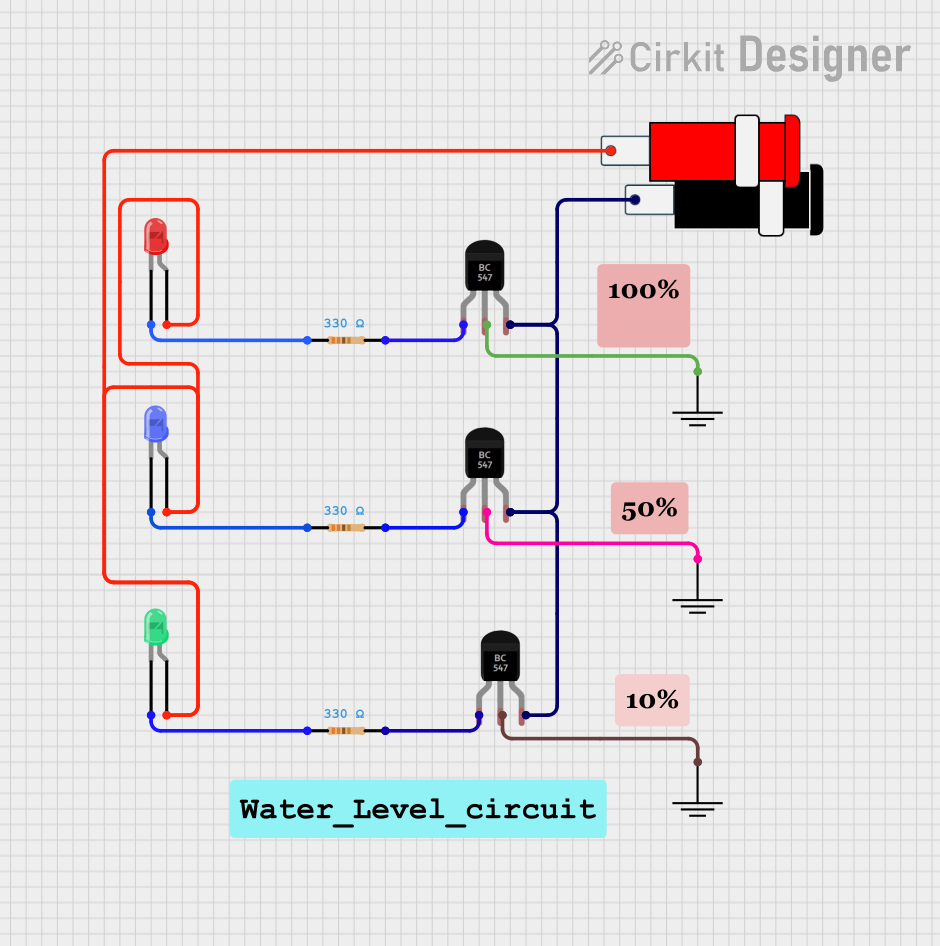 Open Project in Cirkit Designer
 Open Project in Cirkit Designer
Explore Projects Built with M5450 LED Driver
Open Project in Cirkit DesignerOpen Project in Cirkit DesignerOpen Project in Cirkit DesignerOpen Project in Cirkit DesignerCommon Applications
- LED matrix displays
- Digital signage
- Automotive dashboard lighting
- Industrial control panels
- General-purpose LED lighting systems
The M5450 is particularly suited for applications where high efficiency and compact design are critical.
Technical Specifications
Key Technical Details
| Parameter | Value |
|---|---|
| Manufacturer | STMicroelectronics |
| Part Number | M5450 |
| Operating Voltage Range | 4.75V to 15V |
| Maximum Output Current | 20mA per LED channel |
| Number of Outputs | 35 |
| Control Method | Serial Data Input (SPI-like) |
| Operating Temperature | -40°C to +85°C |
| Package Type | DIP-40, SO-40 |
Pin Configuration and Descriptions
The M5450 comes in a 40-pin package. Below is the pin configuration:
Pin Descriptions
| Pin Number | Pin Name | Description |
|---|---|---|
| 1 | VDD | Positive supply voltage (4.75V to 15V). |
| 2-36 | OUT1-OUT35 | LED output pins. Each pin can drive one LED with a maximum current of 20mA. |
| 37 | GND | Ground connection. |
| 38 | DIN | Serial data input for controlling the LEDs. |
| 39 | CLK | Clock input for serial data communication. |
| 40 | LOAD | Latch input to transfer data to the output registers. |
Usage Instructions
How to Use the M5450 in a Circuit
- Power Supply: Connect the VDD pin to a regulated power supply (4.75V to 15V) and the GND pin to ground.
- LED Connections: Connect the LEDs to the OUT1-OUT35 pins. Ensure that the current through each LED does not exceed 20mA.
- Control Signals:
- Use the DIN pin to send serial data to the M5450.
- Provide a clock signal to the CLK pin to synchronize data transfer.
- Use the LOAD pin to latch the data into the output registers.
- Resistor Selection: Use appropriate current-limiting resistors for each LED to prevent overcurrent.
Important Considerations
- Thermal Management: Ensure proper heat dissipation, especially when driving multiple LEDs at high currents.
- Decoupling Capacitor: Place a decoupling capacitor (e.g., 0.1µF) near the VDD pin to reduce noise and improve stability.
- Data Timing: Follow the timing requirements specified in the datasheet for proper serial communication.
Example: Connecting the M5450 to an Arduino UNO
The M5450 can be controlled using an Arduino UNO. Below is an example code snippet to control the brightness of LEDs:
// Define Arduino pins connected to the M5450
#define DATA_PIN 8  // Connect to DIN pin of M5450
#define CLOCK_PIN 9 // Connect to CLK pin of M5450
#define LOAD_PIN 10 // Connect to LOAD pin of M5450

void setup() {
  // Set pins as outputs
  pinMode(DATA_PIN, OUTPUT);
  pinMode(CLOCK_PIN, OUTPUT);
  pinMode(LOAD_PIN, OUTPUT);

  // Initialize pins to LOW
  digitalWrite(DATA_PIN, LOW);
  digitalWrite(CLOCK_PIN, LOW);
  digitalWrite(LOAD_PIN, LOW);
}

void loop() {
  // Example: Turn on LEDs in a pattern
  uint32_t ledPattern = 0b10101010101010101010101010101010; // Example pattern

  sendDataToM5450(ledPattern); // Send data to M5450
  delay(500);                  // Wait for 500ms
}

// Function to send 35-bit data to the M5450
void sendDataToM5450(uint32_t data) {
  digitalWrite(LOAD_PIN, LOW); // Begin data transfer

  for (int i = 34; i >= 0; i--) {
    // Send each bit of the data (MSB first)
    digitalWrite(DATA_PIN, (data >> i) & 0x01);
    digitalWrite(CLOCK_PIN, HIGH); // Clock pulse
    digitalWrite(CLOCK_PIN, LOW);
  }

  digitalWrite(LOAD_PIN, HIGH); // Latch data into output registers
}
Troubleshooting and FAQs
Common Issues and Solutions
LEDs Not Lighting Up:
- Cause: Incorrect wiring or insufficient power supply.
- Solution: Double-check the connections and ensure the power supply meets the voltage and current requirements.
Flickering LEDs:
- Cause: Noise or unstable power supply.
- Solution: Add a decoupling capacitor near the VDD pin and ensure a stable power source.
Incorrect LED Patterns:
- Cause: Data timing issues or incorrect serial communication.
- Solution: Verify the clock and data signals using an oscilloscope. Ensure the Arduino code matches the M5450's timing requirements.
Overheating:
- Cause: Excessive current through LEDs or poor thermal management.
- Solution: Use appropriate current-limiting resistors and ensure proper ventilation or heat sinking.
FAQs
Q: Can the M5450 drive RGB LEDs?
- A: Yes, but each color channel of the RGB LED will require a separate output pin.
Q: What is the maximum number of LEDs the M5450 can drive?
- A: The M5450 can drive up to 35 LEDs.
Q: Can I cascade multiple M5450 ICs for larger LED arrays?
- A: Yes, multiple M5450 ICs can be cascaded by connecting the data output of one IC to the data input of the next.
Q: Is the M5450 compatible with 3.3V microcontrollers?
- A: The M5450 requires a minimum VDD of 4.75V, so level shifters may be needed for 3.3V microcontrollers.
This concludes the documentation for the M5450 LED Driver. For further details, refer to the official datasheet provided by STMicroelectronics.