How to Use SparkFun Qwiic Pro Micro - USB-C: Examples, Pinouts, and Specs
Introduction
The SparkFun Qwiic Pro Micro - USB-C is a versatile development board that harnesses the power of the ATmega32U4 microcontroller. This board is an excellent choice for hobbyists and professionals alike, providing a compact form factor with a USB-C connection for programming and power. The inclusion of Qwiic connectors simplifies the process of integrating various sensors and modules, making it an ideal platform for rapid prototyping and development of electronic projects.
Explore Projects Built with SparkFun Qwiic Pro Micro - USB-C
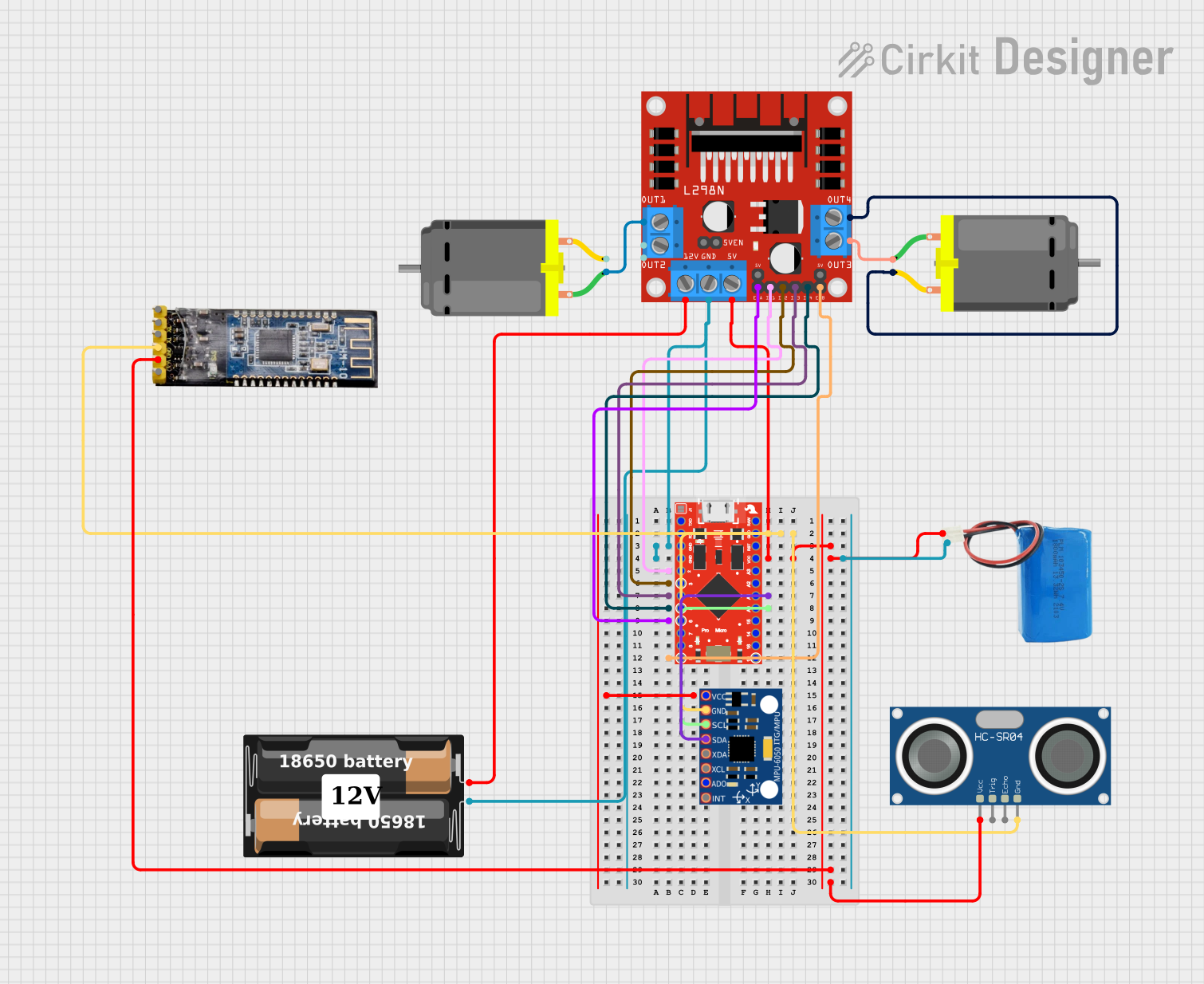
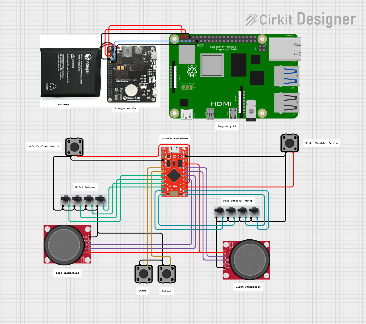
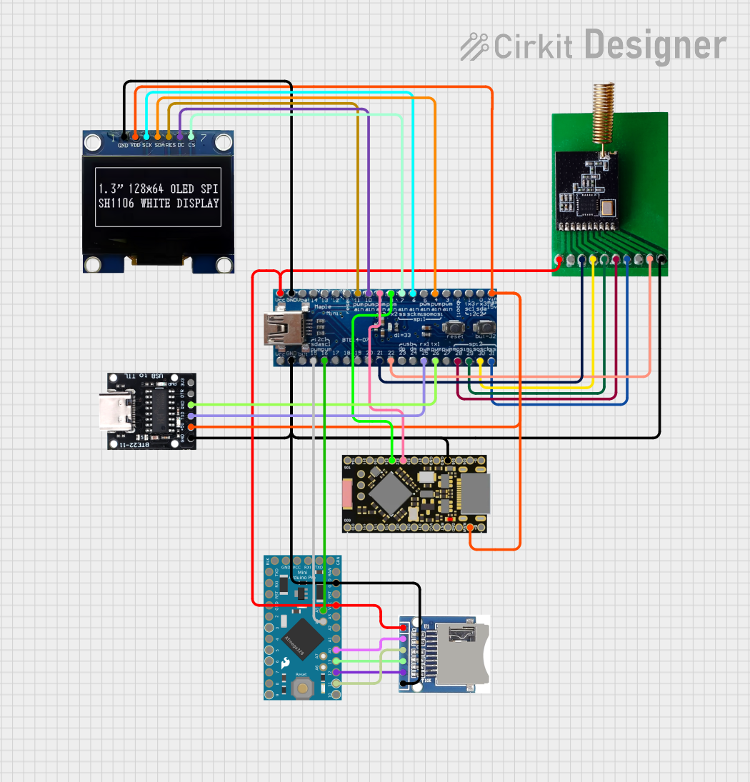

Explore Projects Built with SparkFun Qwiic Pro Micro - USB-C
Common Applications and Use Cases
- Wearable electronics
- USB peripheral development
- Rapid prototyping with Qwiic-enabled I2C devices
- Educational platforms for teaching electronics and programming
- Custom keyboard or game controller projects
Technical Specifications
Key Technical Details
- Microcontroller: ATmega32U4
- Operating Voltage: 3.3V
- Input Voltage: 5V (via USB-C)
- Digital I/O Pins: 12
- PWM Channels: 5
- Analog Input Channels: 4
- DC Current per I/O Pin: 40 mA
- Flash Memory: 32 KB (ATmega32U4) of which 4 KB used by bootloader
- SRAM: 2.5 KB (ATmega32U4)
- EEPROM: 1 KB (ATmega32U4)
- Clock Speed: 8 MHz
- Qwiic Connectors: 2x
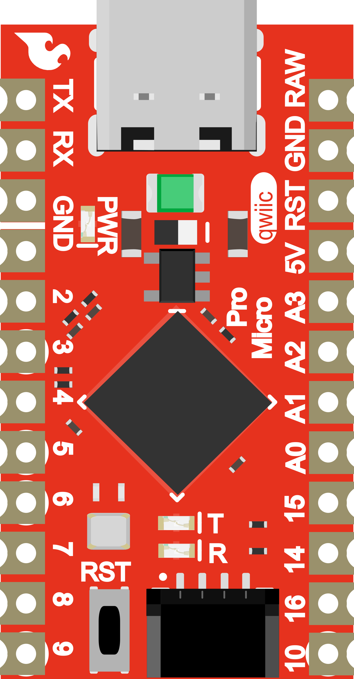
Pin Configuration and Descriptions
| Pin Number | Function | Description |
|---|---|---|
| 1 | TXO | Transmit pin for serial communication |
| 2 | RXI | Receive pin for serial communication |
| 3 | GND | Ground |
| 4 | GND | Ground |
| 5 | 2 | General purpose digital I/O pin |
| 6 | 3 | General purpose digital I/O with PWM |
| ... | ... | ... |
| 23 | A3 | Analog input channel 3 |
| 24 | A2 | Analog input channel 2 |
| 25 | A1 | Analog input channel 1 |
| 26 | A0 | Analog input channel 0 |
| 27 | RST | Reset pin |
| 28 | GND | Ground |
| 29 | RAW | Raw voltage input for VCC |
| 30 | VCC | Positive supply voltage |
Note: This is a partial table for illustration purposes.
Usage Instructions
How to Use the Component in a Circuit
- Powering the Board: Connect the USB-C cable to the board and a computer or USB power source.
- Connecting Qwiic Devices: Attach Qwiic-enabled devices to the Qwiic connectors on the board.
- Programming: Use the Arduino IDE or other compatible software to write and upload sketches to the board.
- I/O Pin Usage: Utilize the digital and analog pins for interfacing with various sensors, actuators, and other components.
Important Considerations and Best Practices
- Ensure that the input voltage does not exceed the recommended 5V.
- When using PWM, be aware of the current limitations of the I/O pins.
- Avoid exposing the board to static electricity or physical stress.
- Always disconnect the board from power sources before making or altering connections.
Example Code for Arduino UNO
// Blink an LED connected to pin 9

void setup() {
  pinMode(9, OUTPUT); // Set pin 9 as an output
}

void loop() {
  digitalWrite(9, HIGH); // Turn the LED on
  delay(1000);           // Wait for a second
  digitalWrite(9, LOW);  // Turn the LED off
  delay(1000);           // Wait for a second
}
Troubleshooting and FAQs
Common Issues
- Board Not Recognized: Ensure the USB-C cable is properly connected and the computer's drivers are up to date.
- Sketch Not Uploading: Check the selected board and port in the Arduino IDE. Ensure the correct drivers are installed.
- Qwiic Device Not Working: Verify that the Qwiic device is correctly connected and compatible with the board.
Solutions and Tips for Troubleshooting
- Driver Installation: Make sure to install the necessary drivers for the board on your computer.
- Cable Check: Use a known good USB-C cable and port.
- IDE Settings: Double-check the board and port settings in your development environment.
- Reset the Board: Press the reset button on the board if it becomes unresponsive.
FAQs
Q: Can I power the board without a USB-C connection? A: Yes, you can supply power through the RAW pin, but ensure the voltage is regulated and does not exceed 5V.
Q: How many Qwiic devices can I connect? A: You can daisy-chain multiple Qwiic devices, but be mindful of the power consumption and I2C address conflicts.
Q: Is the board compatible with all Arduino libraries? A: Most libraries that support the ATmega32U4 should be compatible, but some may require modifications due to the board's specific hardware configuration.