Cirkit Designer
Your all-in-one circuit design IDE
Home /
Component Documentation
How to Use SIM900A Mini: Examples, Pinouts, and Specs
Introduction
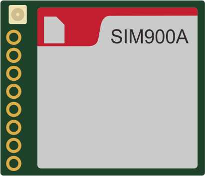
The SIM900A Mini is a compact GSM/GPRS module that enables cellular communication in embedded systems. It allows devices to send and receive SMS messages, make and receive voice calls, and connect to the internet via GPRS. This module is widely used in various applications such as remote data monitoring, IoT devices, automotive applications, and security systems.
Explore Projects Built with SIM900A Mini
Arduino UNO and SIM900A GSM Module for Remote Communication
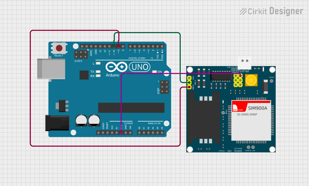
This circuit interfaces an Arduino UNO with a SIM900A GSM module. The Arduino controls the SIM900A via digital pins D9 and D10 for serial communication, while both components share a common ground.
Arduino UNO and SIM900A GSM Module Communication System
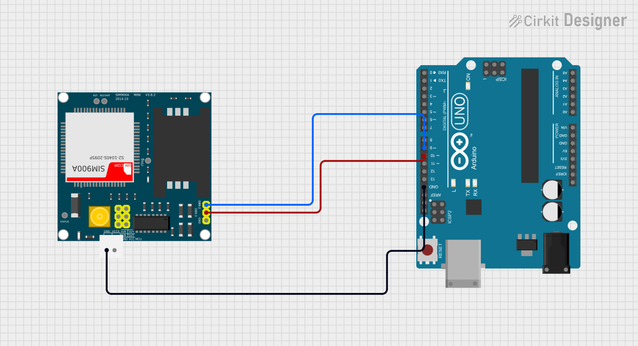
This circuit interfaces an Arduino UNO with a SIM900A GSM module. The Arduino communicates with the SIM900A via digital pins D9 and D10 for serial data transmission and reception, while both devices share a common ground.
Arduino UNO Based GPS and GSM Tracking System
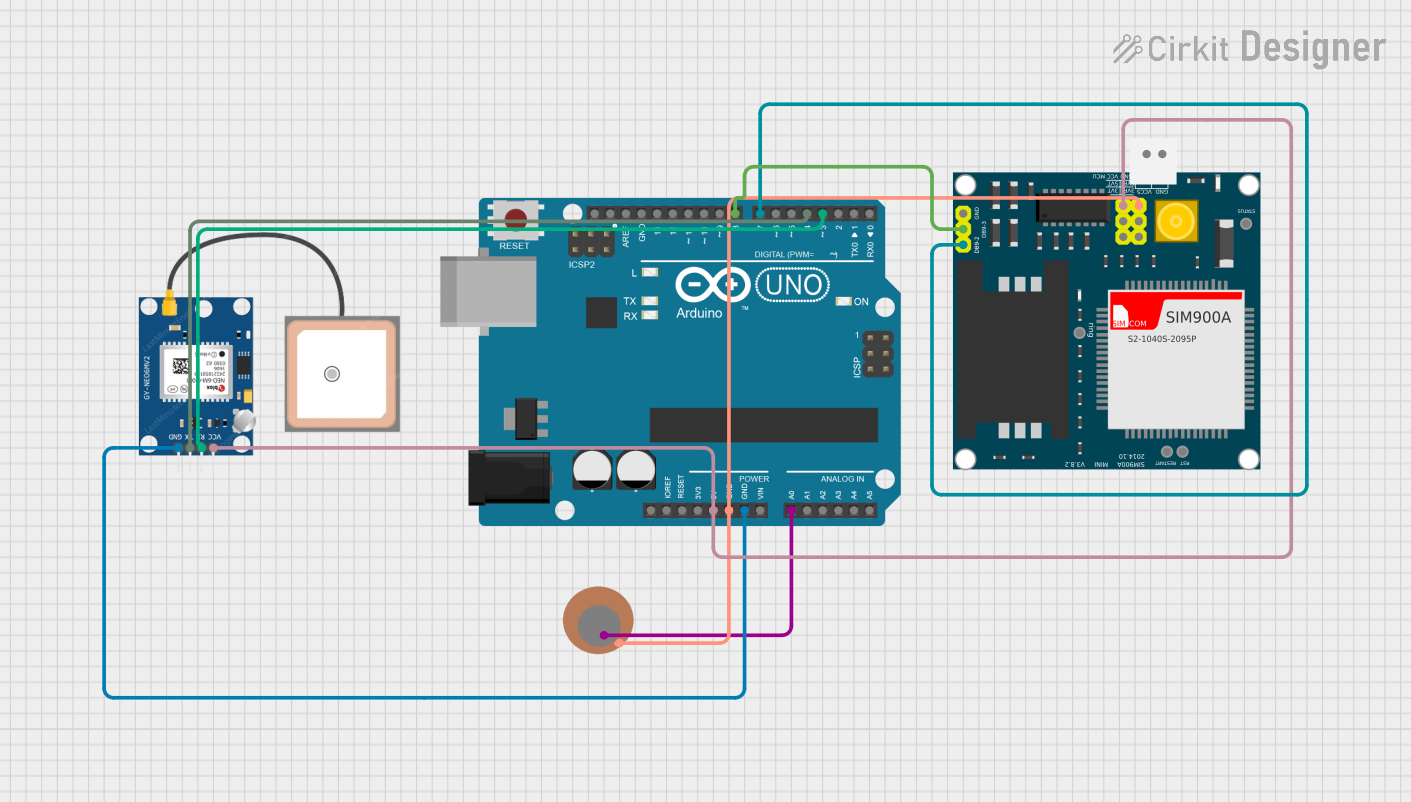
This circuit features an Arduino UNO microcontroller interfaced with a SIM900A GSM module and a GPS NEO 6M module. The Arduino communicates with the SIM900A via digital pins D7 and D8 for TXD and RXD respectively, and with the GPS module via digital pins D3 and D4 for RX and TX. Additionally, a Piezo Sensor is connected to analog pin A0, allowing the Arduino to read vibrations or pressure changes.
Arduino UNO and SIM900A GSM Module for Remote Communication
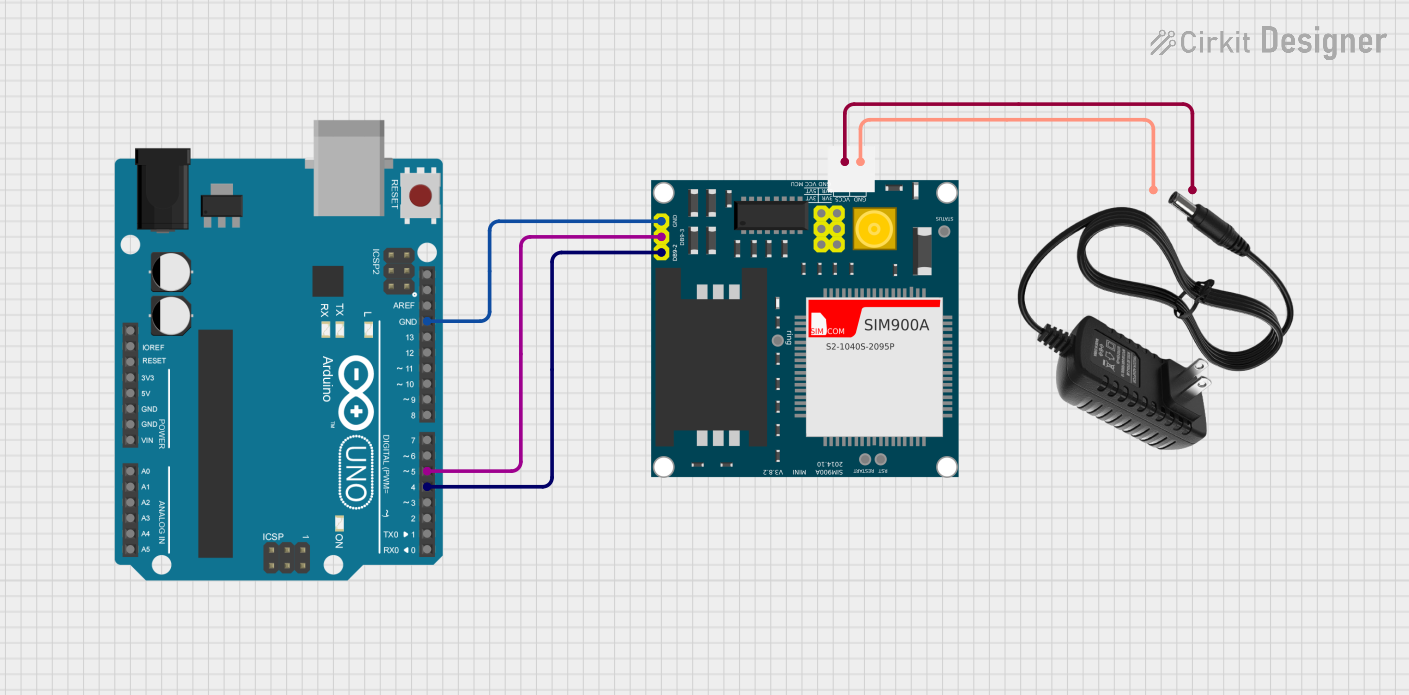
This circuit integrates an Arduino UNO with a SIM900A GSM module, powered by a 12V power supply. The Arduino communicates with the SIM900A via digital pins D4 and D5 for TX and RX respectively, enabling GSM communication capabilities.
Explore Projects Built with SIM900A Mini
Arduino UNO and SIM900A GSM Module for Remote Communication
This circuit interfaces an Arduino UNO with a SIM900A GSM module. The Arduino controls the SIM900A via digital pins D9 and D10 for serial communication, while both components share a common ground.
Arduino UNO and SIM900A GSM Module Communication System
This circuit interfaces an Arduino UNO with a SIM900A GSM module. The Arduino communicates with the SIM900A via digital pins D9 and D10 for serial data transmission and reception, while both devices share a common ground.
Arduino UNO Based GPS and GSM Tracking System
This circuit features an Arduino UNO microcontroller interfaced with a SIM900A GSM module and a GPS NEO 6M module. The Arduino communicates with the SIM900A via digital pins D7 and D8 for TXD and RXD respectively, and with the GPS module via digital pins D3 and D4 for RX and TX. Additionally, a Piezo Sensor is connected to analog pin A0, allowing the Arduino to read vibrations or pressure changes.
Arduino UNO and SIM900A GSM Module for Remote Communication
This circuit integrates an Arduino UNO with a SIM900A GSM module, powered by a 12V power supply. The Arduino communicates with the SIM900A via digital pins D4 and D5 for TX and RX respectively, enabling GSM communication capabilities.
Common Applications and Use Cases
- Remote monitoring and control systems
- IoT devices for smart home automation
- Vehicle tracking and fleet management
- Emergency call systems
- SMS-based remote alerts and notifications
Technical Specifications
Key Technical Details
- Frequency Bands: GSM 900MHz/1800MHz
- GPRS Multi-slot Class: 10/8
- GPRS Mobile Station Class: B
- Compliant to GSM Phase 2/2+
- Supply Voltage Range: 3.4V - 4.5V
- Operating Temperature: -30°C to +80°C
- Sensitivity: -105dBm
- Output Power: Class 4 (2W) for GSM900, Class 1 (1W) for GSM1800
Pin Configuration and Descriptions
| Pin Number | Name | Description |
|---|---|---|
| 1 | VCC | Power supply input (3.4V - 4.5V) |
| 2 | RST | Reset pin, active low |
| 3 | RXD | Serial data receive pin |
| 4 | TXD | Serial data transmit pin |
| 5 | GND | Ground connection |
Usage Instructions
How to Use the Component in a Circuit
- Power Supply: Connect the VCC pin to a stable power source within the specified voltage range and GND to the system ground.
- Serial Communication: Connect the RXD and TXD pins to the microcontroller or computer's TX and RX pins, respectively, for serial communication.
- Antenna: Attach a suitable GSM antenna to the module's antenna connector for signal reception and transmission.
- SIM Card: Insert a SIM card into the SIM card holder to enable cellular network access.
Important Considerations and Best Practices
- Ensure that the power supply is stable and within the specified voltage range to prevent damage.
- Use a level shifter if the microcontroller operates at a different voltage level than the SIM900A Mini.
- Place the module away from noise sources and ensure the antenna has a clear view of the sky for optimal signal reception.
- Follow ESD precautions when handling the module to avoid electrostatic damage.
Troubleshooting and FAQs
Common Issues Users Might Face
- Power Issues: If the module does not power up, check the power supply and connections.
- Signal Problems: Poor signal quality can result from improper antenna placement or SIM card issues.
- Communication Errors: Ensure proper serial communication settings and connections between the module and the microcontroller.
Solutions and Tips for Troubleshooting
- Verify the power supply voltage and current capabilities.
- Check the antenna connections and try repositioning the antenna.
- Confirm that the SIM card is activated and has the appropriate subscription for the intended services.
- Use AT commands to communicate with the module and check its status.
Example Code for Arduino UNO
#include <SoftwareSerial.h>

SoftwareSerial SIM900A(7, 8); // RX, TX

void setup() {
  // Begin serial communication with Arduino and Arduino IDE (Serial Monitor)
  Serial.begin(9600);

  // Begin serial communication with SIM900A Mini and set baud rate
  SIM900A.begin(9600);

  // AT command to set SIM900A to SMS mode
  SIM900A.print("AT+CMGF=1\r");
  delay(100);

  // Set module to send SMS data to serial out upon receipt
  SIM900A.print("AT+CNMI=2,2,0,0,0\r");
  delay(100);
}

void loop() {
  // Check if the SIM900A Mini has sent any data to the Arduino
  if (SIM900A.available()) {
    Serial.write(SIM900A.read()); // Forward what SIM900A Mini has sent to Serial Monitor
  }

  // Check if the Arduino has sent any data to the SIM900A Mini
  if (Serial.available()) {
    SIM900A.write(Serial.read()); // Forward what Serial Monitor has sent to SIM900A Mini
  }
}
Note: This example sets up the SIM900A Mini to send and receive SMS messages. The SoftwareSerial library is used to create a serial connection on pins 7 and 8 of the Arduino UNO. Adjust the pin numbers as needed for your setup.