
How to Use ACS712: Examples, Pinouts, and Specs
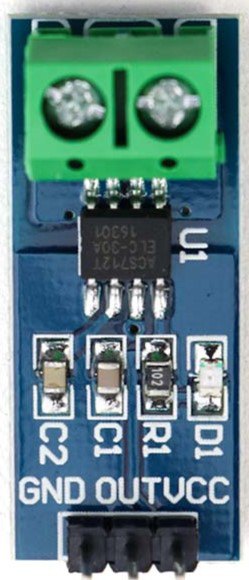
 Design with ACS712 in Cirkit Designer
Introduction
The ACS712 Hall Effect Current Sensor, manufactured by Allegro MicroSystems, is a linear current sensor designed to measure both AC and DC currents. It utilizes the Hall effect principle to provide an analog voltage output proportional to the current flowing through its input terminals. The sensor is widely used in applications requiring current monitoring, such as motor control, power management, and overcurrent protection. Its compact design, electrical isolation, and high accuracy make it a popular choice for both industrial and hobbyist projects.
Explore Projects Built with ACS712
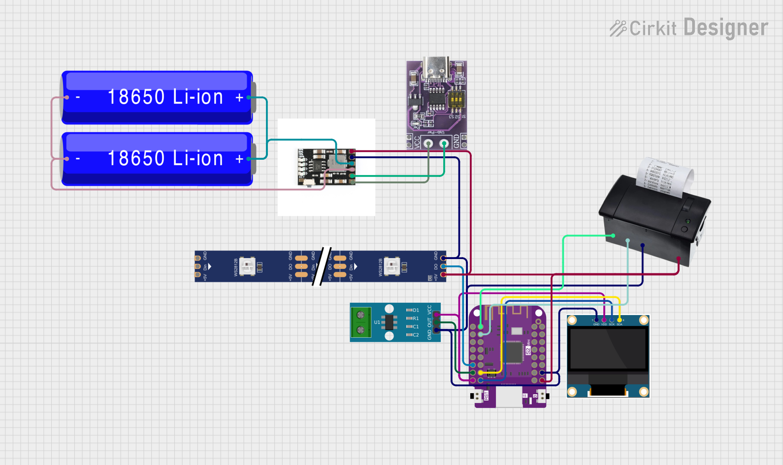 Open Project in Cirkit Designer
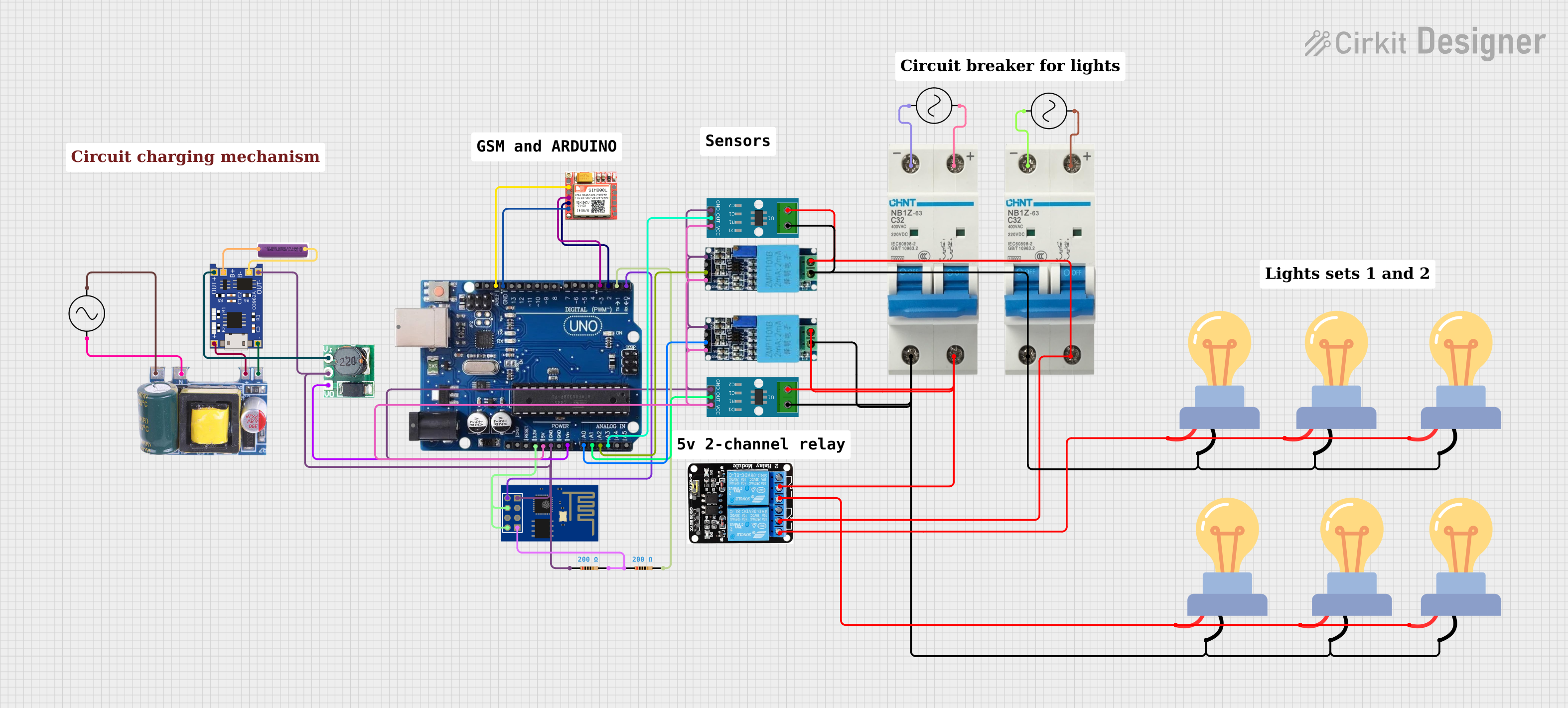 Open Project in Cirkit Designer
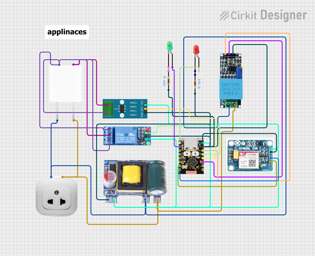 Open Project in Cirkit Designer
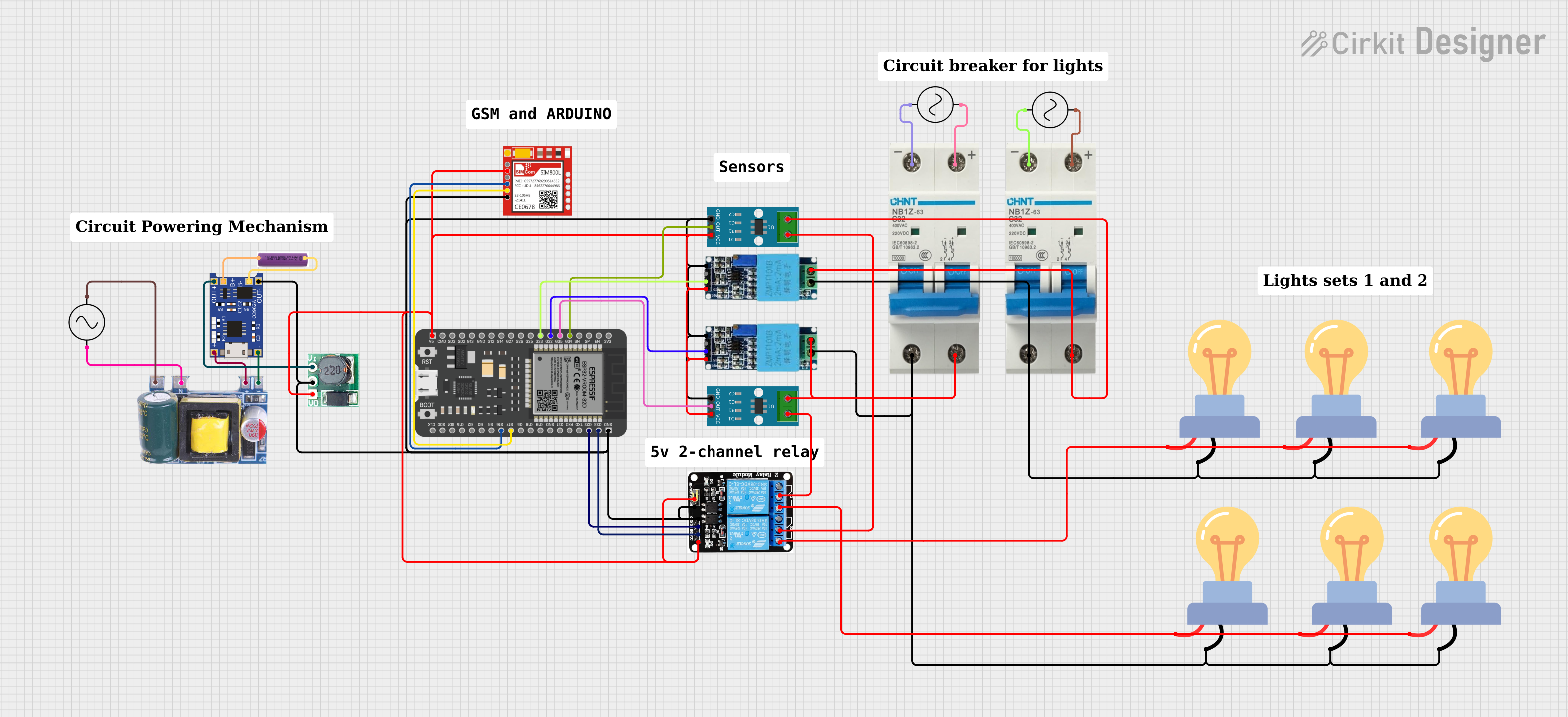 Open Project in Cirkit Designer
Explore Projects Built with ACS712
Open Project in Cirkit DesignerOpen Project in Cirkit DesignerOpen Project in Cirkit DesignerOpen Project in Cirkit DesignerCommon Applications
- Motor current monitoring
- Power supply and battery management
- Overcurrent protection in circuits
- Energy metering
- Home automation systems
- Robotics and IoT projects
Technical Specifications
The ACS712 is available in different variants based on the current range it can measure. Below are the key technical details:
| Parameter | Value |
|---|---|
| Manufacturer | Allegro MicroSystems |
| Part Number | ACS712 |
| Measurement Range | ±5A, ±20A, ±30A (depending on variant) |
| Supply Voltage (Vcc) | 4.5V to 5.5V |
| Output Voltage | Analog (proportional to current) |
| Sensitivity | 185 mV/A (±5A), 100 mV/A (±20A), 66 mV/A (±30A) |
| Bandwidth | 80 kHz |
| Response Time | 5 µs |
| Isolation Voltage | 2.1 kV RMS |
| Operating Temperature Range | -40°C to 85°C |
| Package Type | SOIC-8 |
Pin Configuration and Descriptions
The ACS712 is typically available in an 8-pin SOIC package. Below is the pinout and description:
| Pin Number | Pin Name | Description |
|---|---|---|
| 1, 2 | IP+ | Current input terminal (positive side of the current path) |
| 3, 4 | IP- | Current input terminal (negative side of the current path) |
| 5 | GND | Ground connection |
| 6 | VIOUT | Analog output voltage proportional to the measured current |
| 7 | FILTER | Optional external capacitor connection to set bandwidth |
| 8 | VCC | Supply voltage (4.5V to 5.5V) |
Usage Instructions
How to Use the ACS712 in a Circuit
- Power Supply: Connect the VCC pin to a 5V power source and the GND pin to the ground of your circuit.
- Current Path: Pass the current to be measured through the IP+ and IP- terminals. Ensure the current does not exceed the sensor's rated range.
- Output Signal: Connect the VIOUT pin to an analog input pin of a microcontroller or an ADC (Analog-to-Digital Converter) to read the output voltage.
- Filtering: Optionally, connect a capacitor between the FILTER pin and GND to reduce noise and set the desired bandwidth.
Important Considerations
- Isolation: The ACS712 provides electrical isolation between the current-carrying path and the output signal, making it safe for high-voltage applications.
- Calibration: The output voltage at zero current is typically 2.5V. You may need to calibrate your system to account for this offset.
- Current Direction: Positive current flows from IP+ to IP-, and the output voltage increases above 2.5V. Negative current decreases the output voltage below 2.5V.
- Heat Dissipation: Ensure proper heat dissipation if measuring high currents for extended periods.
Example Code for Arduino UNO
Below is an example of how to use the ACS712 with an Arduino UNO to measure current:
// Include necessary libraries
const int analogPin = A0; // Connect VIOUT to Arduino analog pin A0
const float sensitivity = 0.185; // Sensitivity in V/A (for ±5A variant)
const float zeroCurrentVoltage = 2.5; // Output voltage at 0A (in volts)

void setup() {
  Serial.begin(9600); // Initialize serial communication
}

void loop() {
  int sensorValue = analogRead(analogPin); // Read analog value from ACS712
  float voltage = sensorValue * (5.0 / 1023.0); // Convert ADC value to voltage
  float current = (voltage - zeroCurrentVoltage) / sensitivity;
  // Calculate current in Amperes

  Serial.print("Current: ");
  Serial.print(current, 3); // Print current with 3 decimal places
  Serial.println(" A"); // Append unit

  delay(1000); // Wait for 1 second before next reading
}
Notes:
- Replace the
sensitivityvalue in the code with the appropriate value for your ACS712 variant (e.g., 0.1 for ±20A or 0.066 for ±30A). - Ensure the Arduino's ground is connected to the ACS712's GND pin.
Troubleshooting and FAQs
Common Issues
Incorrect Current Readings:
- Cause: Improper calibration or incorrect sensitivity value.
- Solution: Verify the sensitivity value for your ACS712 variant and recalibrate the system.
No Output Signal:
- Cause: Missing or incorrect power supply connection.
- Solution: Ensure VCC is connected to a 5V source and GND is properly grounded.
High Noise in Output:
- Cause: Lack of filtering or external noise interference.
- Solution: Add a capacitor (e.g., 1nF to 10nF) between the FILTER pin and GND to reduce noise.
Overheating:
- Cause: Exceeding the sensor's current rating.
- Solution: Ensure the current through the sensor does not exceed its rated range.
FAQs
Q1: Can the ACS712 measure both AC and DC currents?
Yes, the ACS712 can measure both AC and DC currents. The output voltage varies proportionally with the instantaneous current.
Q2: What is the maximum current the ACS712 can handle?
The maximum current depends on the variant: ±5A, ±20A, or ±30A. Ensure you select the appropriate variant for your application.
Q3: How do I interpret the output voltage?
At zero current, the output voltage is approximately 2.5V. Positive currents increase the voltage above 2.5V, while negative currents decrease it below 2.5V.
Q4: Can I use the ACS712 with a 3.3V microcontroller?
Yes, but you need to ensure the output voltage range of the ACS712 is compatible with the ADC input range of your microcontroller. You may need a voltage divider or level shifter.
Q5: Is the ACS712 suitable for high-frequency current measurements?
The ACS712 has a bandwidth of 80 kHz, making it suitable for most low- to mid-frequency applications. For higher frequencies, consider alternative sensors with higher bandwidth.