Cirkit Designer Logo
Cirkit Designer
Your all-in-one circuit design IDE
Home / 
Component Documentation

How to Use VL53L7CX: Examples, Pinouts, and Specs

Image of VL53L7CX
Cirkit Designer LogoDesign with VL53L7CX in Cirkit Designer

Introduction

The VL53L7CX is a state-of-the-art time-of-flight (ToF) distance sensor developed by STMicroelectronics. It uses advanced laser technology to measure distances with high precision and speed. This sensor is capable of multi-zone distance measurement, allowing it to detect objects in multiple regions simultaneously. Its ability to function in various lighting conditions makes it ideal for a wide range of applications.

Explore Projects Built with VL53L7CX

Use Cirkit Designer to design, explore, and prototype these projects online. Some projects support real-time simulation. Click "Open Project" to start designing instantly!
Arduino UNO with A9G GSM/GPRS and Dual VL53L1X Distance Sensors
Image of TED CIRCUIT : A project utilizing VL53L7CX in a practical application
This circuit features an Arduino UNO microcontroller interfaced with an A9G GSM/GPRS+GPS/BDS module and two VL53L1X time-of-flight distance sensors. The A9G module is connected to the Arduino via serial communication for GPS and GSM functionalities, while both VL53L1X sensors are connected through I2C with shared SDA and SCL lines and individual SHUT pins for selective sensor activation. The Arduino is programmed to control these peripherals, although the specific functionality is not detailed in the provided code.
Cirkit Designer LogoOpen Project in Cirkit Designer
A-Star 32U4 Mini Controlled Servo with VL53L8CX Time-of-Flight Distance Sensing
Image of Servo con distance sensor: A project utilizing VL53L7CX in a practical application
This circuit features an A-Star 32U4 Mini microcontroller connected to a VL53L8CX Time-of-Flight distance sensor and a servo motor. The microcontroller powers both the sensor and the servo, and it is configured to communicate with the sensor via I2C (using pins 2 and 3 for SDA and SCL, respectively) and to control the servo via a PWM signal on pin 10. The purpose of the circuit is likely to measure distances and respond with movements of the servo based on the sensor readings.
Cirkit Designer LogoOpen Project in Cirkit Designer
Cellular-Enabled IoT Device with Real-Time Clock and Power Management
Image of LRCM PHASE 2 BASIC: A project utilizing VL53L7CX in a practical application
This circuit features a LilyGo-SIM7000G module for cellular communication and GPS functionality, interfaced with an RTC DS3231 for real-time clock capabilities. It includes voltage sensing through two voltage sensor modules, and uses an 8-channel opto-coupler for isolating different parts of the circuit. Power management is handled by a buck converter connected to a DC power source and batteries, with a fuse for protection and a rocker switch for on/off control. Additionally, there's an LED for indication purposes.
Cirkit Designer LogoOpen Project in Cirkit Designer
Arduino 101 Controlled Robotic Arm with VL53L1X Distance Sensor
Image of Mg996R Vl503lox robotic arm: A project utilizing VL53L7CX in a practical application
This circuit features an Arduino 101 microcontroller interfaced with a VL53L1X distance sensor and five MG996R servo motors. The Arduino 101 controls the servos via PWM signals and reads distance measurements from the sensor over I2C, with power supplied through a power jack.
Cirkit Designer LogoOpen Project in Cirkit Designer

Explore Projects Built with VL53L7CX

Use Cirkit Designer to design, explore, and prototype these projects online. Some projects support real-time simulation. Click "Open Project" to start designing instantly!
Image of TED CIRCUIT : A project utilizing VL53L7CX in a practical application
Arduino UNO with A9G GSM/GPRS and Dual VL53L1X Distance Sensors
This circuit features an Arduino UNO microcontroller interfaced with an A9G GSM/GPRS+GPS/BDS module and two VL53L1X time-of-flight distance sensors. The A9G module is connected to the Arduino via serial communication for GPS and GSM functionalities, while both VL53L1X sensors are connected through I2C with shared SDA and SCL lines and individual SHUT pins for selective sensor activation. The Arduino is programmed to control these peripherals, although the specific functionality is not detailed in the provided code.
Cirkit Designer LogoOpen Project in Cirkit Designer
Image of Servo con distance sensor: A project utilizing VL53L7CX in a practical application
A-Star 32U4 Mini Controlled Servo with VL53L8CX Time-of-Flight Distance Sensing
This circuit features an A-Star 32U4 Mini microcontroller connected to a VL53L8CX Time-of-Flight distance sensor and a servo motor. The microcontroller powers both the sensor and the servo, and it is configured to communicate with the sensor via I2C (using pins 2 and 3 for SDA and SCL, respectively) and to control the servo via a PWM signal on pin 10. The purpose of the circuit is likely to measure distances and respond with movements of the servo based on the sensor readings.
Cirkit Designer LogoOpen Project in Cirkit Designer
Image of LRCM PHASE 2 BASIC: A project utilizing VL53L7CX in a practical application
Cellular-Enabled IoT Device with Real-Time Clock and Power Management
This circuit features a LilyGo-SIM7000G module for cellular communication and GPS functionality, interfaced with an RTC DS3231 for real-time clock capabilities. It includes voltage sensing through two voltage sensor modules, and uses an 8-channel opto-coupler for isolating different parts of the circuit. Power management is handled by a buck converter connected to a DC power source and batteries, with a fuse for protection and a rocker switch for on/off control. Additionally, there's an LED for indication purposes.
Cirkit Designer LogoOpen Project in Cirkit Designer
Image of Mg996R Vl503lox robotic arm: A project utilizing VL53L7CX in a practical application
Arduino 101 Controlled Robotic Arm with VL53L1X Distance Sensor
This circuit features an Arduino 101 microcontroller interfaced with a VL53L1X distance sensor and five MG996R servo motors. The Arduino 101 controls the servos via PWM signals and reads distance measurements from the sensor over I2C, with power supplied through a power jack.
Cirkit Designer LogoOpen Project in Cirkit Designer

Common Applications and Use Cases

  • Robotics for obstacle detection and navigation
  • Drones for altitude measurement and collision avoidance
  • Smart home devices, such as automated doors and lighting systems
  • Gesture recognition in consumer electronics
  • Industrial automation and safety systems

Technical Specifications

The VL53L7CX offers impressive performance and flexibility. Below are its key technical details:

Parameter Value
Operating Voltage 2.8 V (typical)
Interface I²C (up to 1 MHz)
Measurement Range 0.1 m to 4 m (depending on conditions)
Multi-Zone Capability Up to 64 zones (8x8 grid)
Field of View (FoV) 63° x 63°
Distance Accuracy ±5 mm (typical, under optimal conditions)
Operating Temperature Range -30°C to +85°C
Power Consumption 5.4 mW (typical in ranging mode)
Dimensions 4.4 mm x 2.4 mm x 1.0 mm

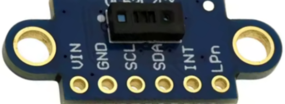
Pin Configuration and Descriptions

The VL53L7CX is typically provided in a compact LGA package. Below is the pin configuration:

Pin Name Type Description
GND Ground Ground connection
VDD Power Supply Main power supply (2.8 V typical)
SDA I²C Data Line Serial data line for I²C communication
SCL I²C Clock Line Serial clock line for I²C communication
GPIO1 Input/Output General-purpose I/O pin (can be used for interrupts or other signals)
XSHUT Input Shutdown pin (active low) to enable or disable the sensor

Usage Instructions

The VL53L7CX is straightforward to integrate into a circuit, thanks to its I²C interface and compact design. Below are the steps and considerations for using the sensor:
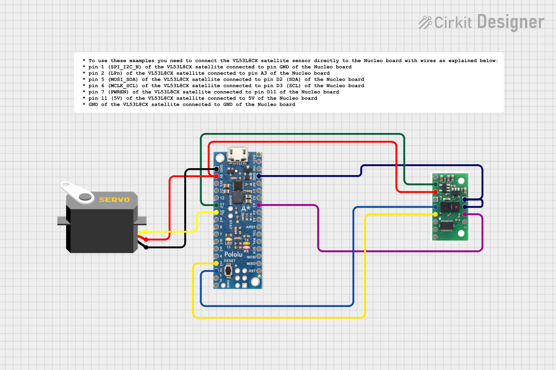
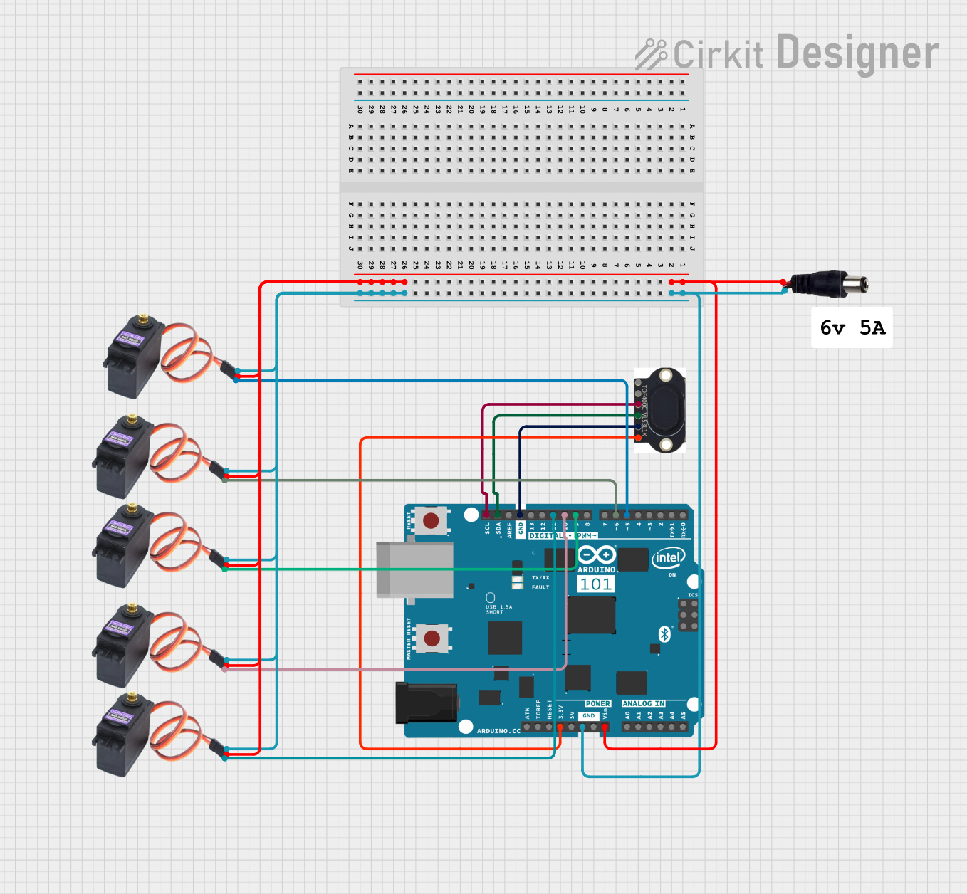
Circuit Connection

  1. Connect the VDD pin to a 2.8 V power supply.
  2. Connect the GND pin to the ground of your circuit.
  3. Connect the SDA and SCL pins to the corresponding I²C data and clock lines of your microcontroller.
  4. Optionally, connect the XSHUT pin to a GPIO pin on your microcontroller to control the sensor's power state.
  5. Use pull-up resistors (typically 4.7 kΩ) on the SDA and SCL lines if not already present on your board.

Important Considerations

  • Ensure the I²C bus voltage matches the sensor's voltage levels (2.8 V).
  • Avoid exposing the sensor to direct sunlight or reflective surfaces, as this may affect accuracy.
  • Use a stable power supply to minimize noise and ensure reliable measurements.

Example Code for Arduino UNO

Below is an example of how to use the VL53L7CX with an Arduino UNO. This code assumes you are using a library such as the VL53L7CX library provided by ST.

#include <Wire.h>
#include <VL53L7CX.h> // Include the VL53L7CX library

VL53L7CX sensor; // Create a sensor object

void setup() {
  Serial.begin(9600); // Initialize serial communication
  Wire.begin();       // Initialize I²C communication

  // Initialize the VL53L7CX sensor
  if (!sensor.begin()) {
    Serial.println("Failed to initialize VL53L7CX sensor!");
    while (1); // Halt execution if initialization fails
  }

  Serial.println("VL53L7CX initialized successfully.");
}

void loop() {
  uint16_t distances[64]; // Array to store distances for 64 zones

  // Perform a distance measurement
  if (sensor.getDistances(distances)) {
    Serial.println("Distance measurements (in mm):");
    for (int i = 0; i < 64; i++) {
      Serial.print(distances[i]);
      Serial.print(" ");
      if ((i + 1) % 8 == 0) Serial.println(); // Print 8 values per line
    }
    Serial.println();
  } else {
    Serial.println("Failed to read distances.");
  }

  delay(500); // Wait 500 ms before the next measurement
}

Notes on the Code

  • The VL53L7CX library must be installed in your Arduino IDE. You can find it on GitHub or the Arduino Library Manager.
  • The getDistances() function retrieves distance measurements for all 64 zones in millimeters.

Troubleshooting and FAQs

Common Issues

  1. Sensor Not Detected on I²C Bus

    • Ensure the SDA and SCL lines are correctly connected.
    • Verify that pull-up resistors are present on the I²C lines.
    • Check the I²C address of the sensor (default is 0x52).
  2. Inaccurate Distance Measurements

    • Avoid reflective or transparent surfaces in the sensor's field of view.
    • Ensure the sensor is not exposed to excessive ambient light.
  3. Sensor Fails to Initialize

    • Verify the power supply voltage is 2.8 V.
    • Check the connection to the XSHUT pin (ensure it is not floating).

Tips for Troubleshooting

  • Use an I²C scanner sketch to confirm the sensor's address.
  • Test the sensor in a controlled environment to rule out external interference.
  • Refer to the VL53L7CX datasheet for detailed electrical and timing requirements.

By following this documentation, you should be able to successfully integrate and use the VL53L7CX in your projects.