How to Use BMS: Examples, Pinouts, and Specs
Introduction
The HELTEC Battery Management System (BMS) is an advanced electronic system designed to manage rechargeable batteries effectively. It monitors the battery's state, calculates secondary data (such as charge and discharge rates), reports critical information, and controls the battery's operating environment. By ensuring safe operation, optimizing performance, and extending battery life, the HELTEC BMS is an essential component for modern battery-powered systems.
Explore Projects Built with BMS


Explore Projects Built with BMS
Common Applications and Use Cases
- Electric vehicles (EVs) and hybrid electric vehicles (HEVs)
- Renewable energy storage systems (e.g., solar and wind energy)
- Uninterruptible power supplies (UPS)
- Consumer electronics (e.g., laptops, smartphones, and power banks)
- Industrial equipment and robotics
Technical Specifications
The HELTEC BMS is designed to support a wide range of battery chemistries, including lithium-ion (Li-ion), lithium iron phosphate (LiFePO4), and more. Below are the key technical details:
General Specifications
| Parameter | Value |
|---|---|
| Input Voltage Range | 3.7V to 60V |
| Maximum Current | 100A |
| Supported Battery Types | Li-ion, LiFePO4, NiMH, etc. |
| Operating Temperature | -20°C to 60°C |
| Communication Protocols | UART, I2C, CAN |
| Balancing Method | Passive or Active Balancing |
| Protection Features | Overcharge, Overdischarge, |
| Overcurrent, Short Circuit |
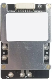
Pin Configuration and Descriptions
| Pin Number | Pin Name | Description |
|---|---|---|
| 1 | B+ | Battery positive terminal |
| 2 | B- | Battery negative terminal |
| 3 | P+ | Load/charger positive terminal |
| 4 | P- | Load/charger negative terminal |
| 5 | COMM_TX | Communication transmit pin (UART/I2C/CAN) |
| 6 | COMM_RX | Communication receive pin (UART/I2C/CAN) |
| 7 | TEMP | Temperature sensor input |
| 8 | BAL_N (1-N) | Balancing pins for individual battery cells |
Usage Instructions
How to Use the HELTEC BMS in a Circuit
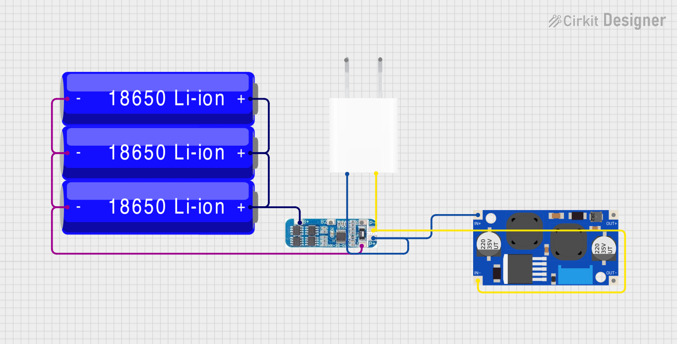
Connect the Battery Pack:
- Connect the battery pack's positive terminal to the
B+pin and the negative terminal to theB-pin. - Ensure the connections are secure and match the voltage range supported by the BMS.
- Connect the battery pack's positive terminal to the
Connect the Load and Charger:
- Attach the load's positive terminal to the
P+pin and the negative terminal to theP-pin. - Similarly, connect the charger to the same
P+andP-terminals.
- Attach the load's positive terminal to the
Temperature Sensor:
- If required, connect a compatible temperature sensor to the
TEMPpin to monitor the battery's temperature.
- If required, connect a compatible temperature sensor to the
Communication Interface:
- Use the
COMM_TXandCOMM_RXpins to interface with a microcontroller or external monitoring system via UART, I2C, or CAN protocols.
- Use the
Cell Balancing:
- For multi-cell battery packs, connect the balancing wires to the
BAL_Npins corresponding to each cell.
- For multi-cell battery packs, connect the balancing wires to the
Important Considerations and Best Practices
- Voltage Compatibility: Ensure the battery pack's voltage is within the BMS's supported range.
- Wiring Order: Always connect the battery pack before connecting the load or charger to avoid potential damage.
- Heat Dissipation: Install the BMS in a well-ventilated area to prevent overheating.
- Firmware Updates: Check for firmware updates from HELTEC to ensure optimal performance and compatibility.
- Safety Precautions: Avoid short circuits and ensure proper insulation of all connections.
Example: Using the HELTEC BMS with an Arduino UNO
Below is an example of interfacing the HELTEC BMS with an Arduino UNO via UART to monitor battery voltage and state of charge (SOC):
#include <SoftwareSerial.h>

// Define RX and TX pins for communication with the BMS
SoftwareSerial bmsSerial(10, 11); // RX = Pin 10, TX = Pin 11

void setup() {
  Serial.begin(9600); // Initialize serial monitor
  bmsSerial.begin(9600); // Initialize BMS communication

  Serial.println("HELTEC BMS Monitoring System");
}

void loop() {
  if (bmsSerial.available()) {
    // Read data from the BMS
    String bmsData = bmsSerial.readString();

    // Display the received data on the serial monitor
    Serial.println("BMS Data: " + bmsData);
  }

  delay(500); // Wait for 500ms before the next read
}
Troubleshooting and FAQs
Common Issues and Solutions
BMS Not Powering On:
- Cause: Incorrect wiring or insufficient input voltage.
- Solution: Verify all connections and ensure the battery pack's voltage is within the supported range.
Overheating:
- Cause: High current draw or poor ventilation.
- Solution: Reduce the load current and ensure proper airflow around the BMS.
Communication Failure:
- Cause: Incorrect baud rate or wiring.
- Solution: Check the communication protocol settings and ensure proper connections to the
COMM_TXandCOMM_RXpins.
Unbalanced Cells:
- Cause: Faulty balancing connections or damaged cells.
- Solution: Inspect the balancing wires and replace any damaged cells.
FAQs
Q: Can the HELTEC BMS support 24V battery packs?
- A: Yes, as long as the total voltage is within the 3.7V to 60V range.
Q: Does the BMS support active cell balancing?
- A: Yes, the HELTEC BMS supports both passive and active balancing methods.
Q: How do I update the BMS firmware?
- A: Visit the HELTEC website for firmware updates and follow the provided instructions.
Q: Can I use the BMS without a temperature sensor?
- A: Yes, but it is recommended to use a temperature sensor for enhanced safety and performance monitoring.