How to Use Reciver wireless power coil: Examples, Pinouts, and Specs
Introduction
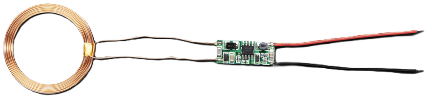
The Wireless Power Receiver Coil is a crucial component in wireless power transfer systems. It is designed to receive power wirelessly from a transmitter coil, making it an essential part of wireless charging systems for various devices such as smartphones, wearable gadgets, and other electronic devices. This component eliminates the need for physical connectors, providing a more convenient and efficient way to charge devices.
Explore Projects Built with Reciver wireless power coil

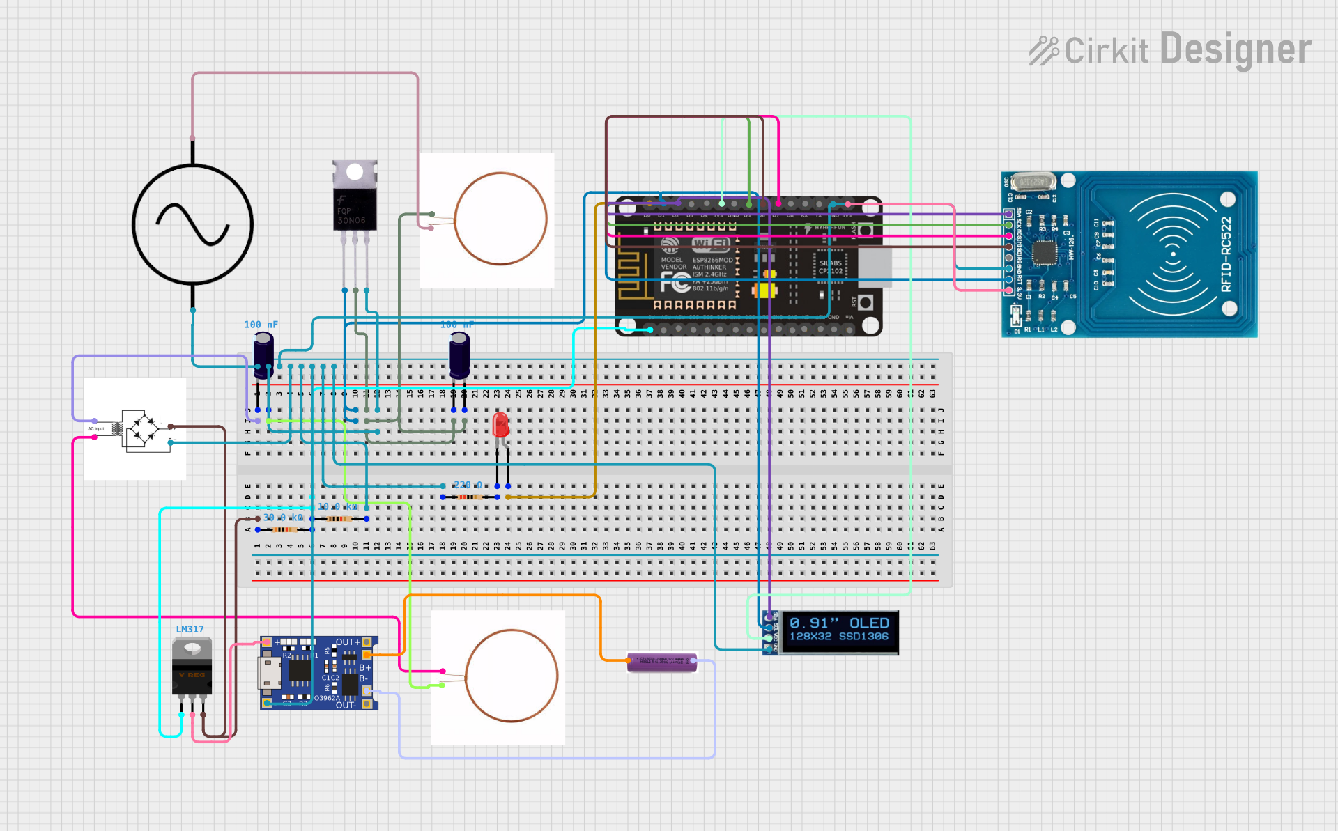
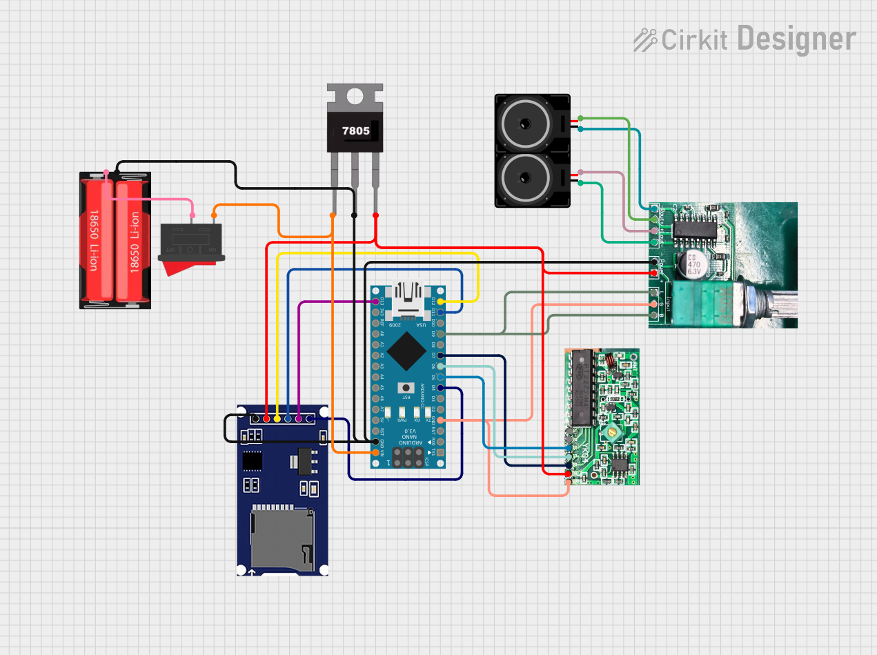

Explore Projects Built with Reciver wireless power coil
Technical Specifications
Key Technical Details
| Parameter | Value |
|---|---|
| Input Voltage | 5V - 12V |
| Output Voltage | 5V |
| Output Current | Up to 1A |
| Power Rating | Up to 5W |
| Operating Frequency | 100 kHz - 205 kHz |
| Efficiency | Up to 80% |
| Coil Inductance | 6.3 µH |
| Coil Resistance | 0.1 Ω |
| Dimensions | 50mm x 50mm x 2mm |
Pin Configuration and Descriptions
| Pin Number | Pin Name | Description |
|---|---|---|
| 1 | VCC | Power input (5V - 12V) |
| 2 | GND | Ground |
| 3 | OUT+ | Positive output voltage (5V) |
| 4 | OUT- | Negative output voltage (Ground) |
Usage Instructions
How to Use the Component in a Circuit
- Power Supply Connection: Connect the VCC pin to a power supply that provides a voltage between 5V and 12V. Connect the GND pin to the ground of the power supply.
- Output Connection: Connect the OUT+ pin to the positive terminal of the device you want to power. Connect the OUT- pin to the ground terminal of the device.
- Placement: Ensure that the receiver coil is aligned with the transmitter coil for optimal power transfer. The distance between the coils should be minimal to maximize efficiency.
Important Considerations and Best Practices
- Alignment: Proper alignment between the transmitter and receiver coils is crucial for efficient power transfer. Misalignment can lead to reduced efficiency and increased heat generation.
- Distance: Keep the distance between the coils as small as possible. The efficiency of power transfer decreases significantly with increasing distance.
- Heat Management: Ensure adequate ventilation around the receiver coil to prevent overheating. Overheating can damage the coil and reduce its lifespan.
- Interference: Avoid placing metal objects between the transmitter and receiver coils as they can interfere with the magnetic field and reduce efficiency.
Troubleshooting and FAQs
Common Issues and Solutions
No Power Output
- Solution: Check the power supply connection to ensure that the VCC and GND pins are correctly connected. Verify that the transmitter coil is powered and properly aligned with the receiver coil.
Low Efficiency
- Solution: Ensure that the receiver coil is properly aligned with the transmitter coil. Reduce the distance between the coils. Check for any metal objects that might be interfering with the magnetic field.
Overheating
- Solution: Ensure adequate ventilation around the receiver coil. Check the power rating of the connected device to ensure it does not exceed the receiver coil's power rating.
FAQs
Q1: Can I use the receiver coil with any transmitter coil?
- A1: The receiver coil is designed to work with transmitter coils operating within the 100 kHz - 205 kHz frequency range. Ensure that the transmitter coil operates within this range for optimal performance.
Q2: What is the maximum distance between the transmitter and receiver coils?
- A2: The maximum distance for efficient power transfer is typically around 5mm. Increasing the distance beyond this can significantly reduce efficiency.
Q3: Can I use the receiver coil to charge multiple devices simultaneously?
- A3: The receiver coil is designed to power a single device. Charging multiple devices simultaneously may exceed the power rating and reduce efficiency.
Example Code for Arduino UNO
If you are using the receiver coil with an Arduino UNO to power a small device, you can use the following code to monitor the voltage output:
const int voltagePin = A0; // Analog pin to read voltage

void setup() {
  Serial.begin(9600); // Initialize serial communication
}

void loop() {
  int sensorValue = analogRead(voltagePin); // Read the analog input
  float voltage = sensorValue * (5.0 / 1023.0); // Convert to voltage
  Serial.print("Voltage: ");
  Serial.print(voltage);
  Serial.println(" V");
  delay(1000); // Wait for 1 second before next reading
}
This code reads the voltage from the receiver coil and prints it to the serial monitor. Ensure that the voltage pin is connected to the OUT+ pin of the receiver coil and the ground of the Arduino is connected to the OUT- pin of the receiver coil.
This documentation provides a comprehensive guide to using the Wireless Power Receiver Coil. Whether you are a beginner or an experienced user, following these instructions and best practices will help you achieve optimal performance and efficiency in your wireless power transfer projects.