How to Use Resistor: Examples, Pinouts, and Specs
Introduction
A resistor is a passive electrical component that limits or regulates the flow of electrical current in a circuit. It is characterized by its resistance value, measured in ohms (Ω). Resistors are fundamental components in electronics and are used to control voltage and current levels, divide voltages, and protect sensitive components from excessive current.
Explore Projects Built with Resistor
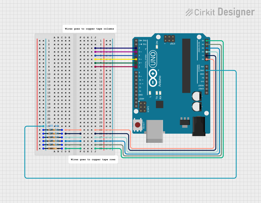
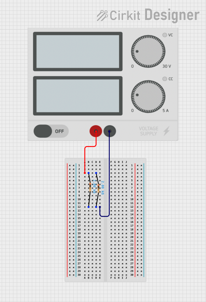
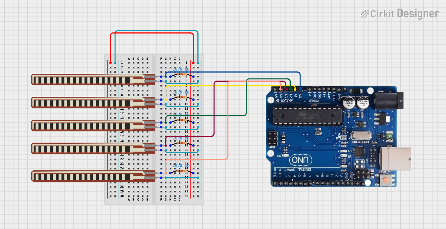
Explore Projects Built with Resistor
Common Applications and Use Cases
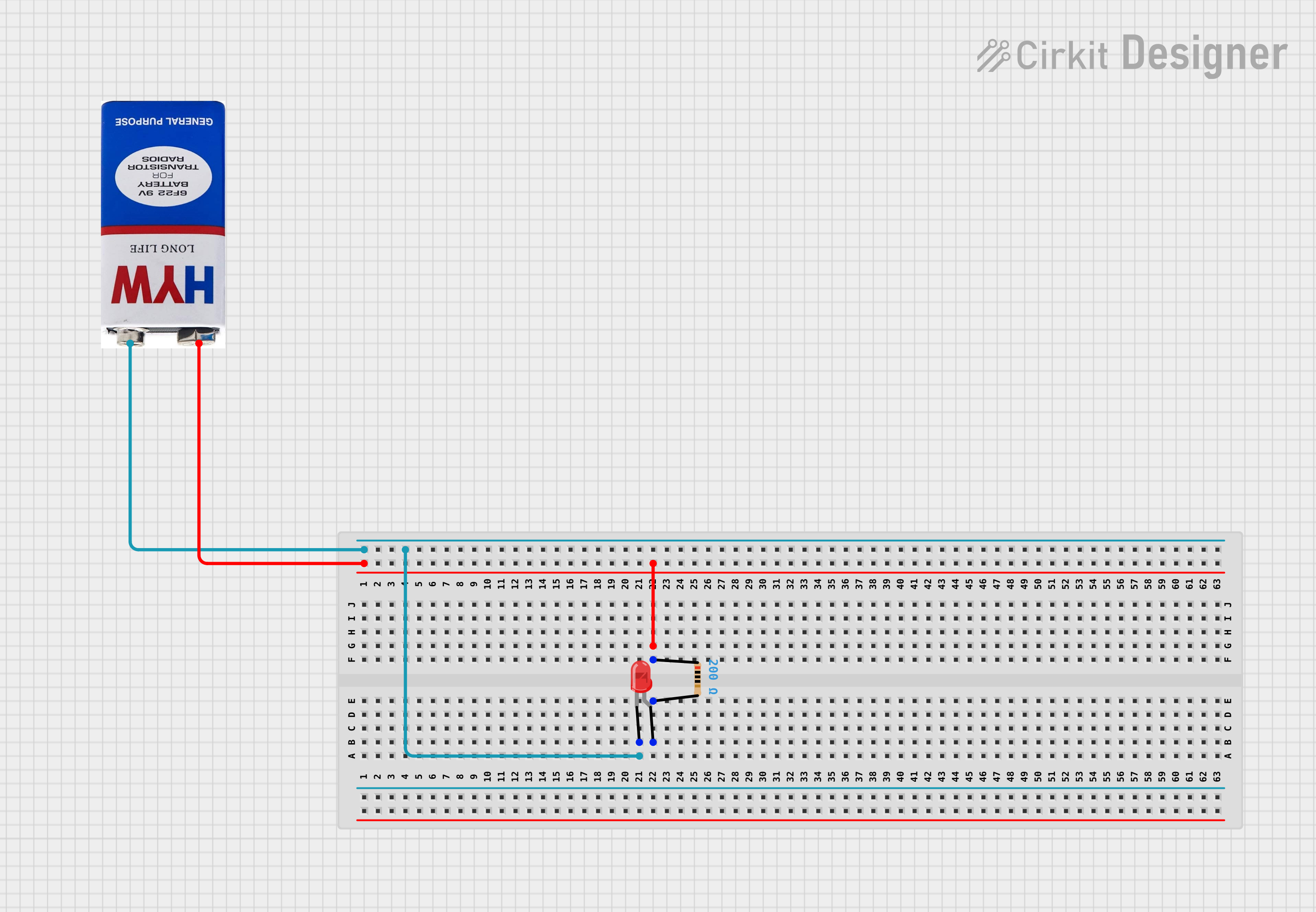
- Current limiting in LED circuits
- Voltage division in potential divider circuits
- Pull-up or pull-down resistors in digital circuits
- Biasing transistors in amplifier circuits
- Protection of components from overcurrent
- Signal conditioning in analog circuits
Technical Specifications
Key Technical Details
- Resistance Range: Typically from 0.1 Ω to several MΩ
- Power Ratings: Commonly 1/8 W, 1/4 W, 1/2 W, 1 W, and higher
- Tolerance: ±1% (precision resistors), ±5%, ±10% (general-purpose resistors)
- Temperature Coefficient: Typically ±100 ppm/°C to ±500 ppm/°C
- Material Types: Carbon film, metal film, wire-wound, and thick/thin film
Pin Configuration and Descriptions
Resistors are non-polarized components, meaning they do not have a specific orientation in a circuit. They typically have two leads, as shown below:
| Pin Number | Description |
|---|---|
| 1 | First terminal for connection |
| 2 | Second terminal for connection |
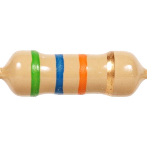
Color Code Chart (for 4-band resistors)
Resistors often use a color code to indicate their resistance value. Below is a simplified chart:
| Band Color | Digit Value | Multiplier (Ω) | Tolerance (%) |
|---|---|---|---|
| Black | 0 | 1 | N/A |
| Brown | 1 | 10 | ±1% |
| Red | 2 | 100 | ±2% |
| Orange | 3 | 1,000 | N/A |
| Yellow | 4 | 10,000 | N/A |
| Green | 5 | 100,000 | ±0.5% |
| Blue | 6 | 1,000,000 | ±0.25% |
| Violet | 7 | 10,000,000 | ±0.1% |
| Gray | 8 | N/A | ±0.05% |
| White | 9 | N/A | N/A |
Usage Instructions
How to Use a Resistor in a Circuit
- Determine the Required Resistance: Use Ohm's Law (V = IR) to calculate the resistance needed for your application.
- Select the Resistor: Choose a resistor with the appropriate resistance value, power rating, and tolerance.
- Connect the Resistor: Place the resistor in series or parallel, depending on the circuit design. Resistors are non-polarized, so orientation does not matter.
- Verify Connections: Ensure the resistor is securely connected to the circuit and that the resistance value matches the design requirements.
Important Considerations and Best Practices
- Power Rating: Ensure the resistor's power rating exceeds the power it will dissipate in the circuit. Use the formula ( P = I^2R ) or ( P = V^2/R ) to calculate power dissipation.
- Tolerance: For precision applications, use resistors with a low tolerance (e.g., ±1%).
- Temperature Effects: Be aware of the resistor's temperature coefficient, as resistance can vary with temperature.
- Series and Parallel Configurations:
- In series: Total resistance ( R_{total} = R_1 + R_2 + \dots + R_n )
- In parallel: Total resistance ( R_{total} = 1 / (1/R_1 + 1/R_2 + \dots + 1/R_n) )
Example: Using a Resistor with an Arduino UNO
Below is an example of using a resistor to limit current for an LED connected to an Arduino UNO:
// Example: LED with current-limiting resistor
// Connect the LED anode (+) to pin 13 of Arduino through a 220Ω resistor.
// Connect the LED cathode (-) to GND.

int ledPin = 13; // Pin connected to the LED

void setup() {
  pinMode(ledPin, OUTPUT); // Set pin 13 as an output
}

void loop() {
  digitalWrite(ledPin, HIGH); // Turn the LED on
  delay(1000);                // Wait for 1 second
  digitalWrite(ledPin, LOW);  // Turn the LED off
  delay(1000);                // Wait for 1 second
}
Troubleshooting and FAQs
Common Issues and Solutions
Resistor Overheating:
- Cause: Power dissipation exceeds the resistor's power rating.
- Solution: Use a resistor with a higher power rating or reduce the current/voltage in the circuit.
Incorrect Resistance Value:
- Cause: Misreading the color code or using the wrong resistor.
- Solution: Double-check the color code or measure the resistance with a multimeter.
Circuit Not Working as Expected:
- Cause: Incorrect resistor placement or value.
- Solution: Verify the resistor's connections and ensure the resistance matches the circuit design.
LED Not Lighting Up:
- Cause: Resistor value too high, limiting current excessively.
- Solution: Use a lower resistance value to allow sufficient current for the LED.
FAQs
Q: Can I use multiple resistors to achieve a specific resistance value?
- A: Yes, you can combine resistors in series or parallel to achieve the desired resistance.
Q: How do I calculate the power dissipation of a resistor?
- A: Use the formula ( P = I^2R ) or ( P = V^2/R ), where ( P ) is power, ( I ) is current, and ( R ) is resistance.
Q: What happens if I use a resistor with a lower power rating than required?
- A: The resistor may overheat, potentially causing damage or failure.
Q: Are resistors polarized?
- A: No, resistors are non-polarized and can be connected in either direction.
This documentation provides a comprehensive guide to understanding and using resistors in electronic circuits.