
How to Use LD1020: Examples, Pinouts, and Specs
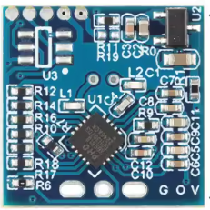
 Design with LD1020 in Cirkit Designer
Introduction
The LD1020 is a low-dropout (LDO) voltage regulator designed to provide a stable and regulated output voltage with a minimal input-output voltage difference. This makes it ideal for applications where power efficiency is critical, such as battery-powered devices. The LD1020 ensures reliable performance in low-voltage environments and is commonly used in portable electronics, microcontroller-based systems, and power-sensitive circuits.
Explore Projects Built with LD1020
 Open Project in Cirkit Designer
 Open Project in Cirkit Designer
 Open Project in Cirkit Designer
 Open Project in Cirkit Designer
Explore Projects Built with LD1020
Open Project in Cirkit DesignerOpen Project in Cirkit DesignerOpen Project in Cirkit DesignerOpen Project in Cirkit DesignerCommon Applications
- Battery-powered devices (e.g., wearables, IoT devices)
- Microcontroller power supply regulation
- Portable electronics
- Low-noise analog circuits
- Post-regulation for switching power supplies
Technical Specifications
The LD1020 is available in various fixed output voltage options and supports a wide range of input voltages. Below are the key technical details:
Key Parameters
| Parameter | Value |
|---|---|
| Input Voltage Range | 2.5V to 16V |
| Output Voltage Options | 1.8V, 3.3V, 5.0V (fixed) |
| Output Current | Up to 1A |
| Dropout Voltage | 0.2V (typical at 1A load) |
| Quiescent Current | 50 µA (typical) |
| Output Voltage Accuracy | ±2% |
| Operating Temperature | -40°C to +125°C |
| Package Options | TO-220, SOT-223, SOT-89 |
Pin Configuration
The LD1020 is available in multiple package types. Below is the pin configuration for the most common package, TO-220:
| Pin Number | Pin Name | Description |
|---|---|---|
| 1 | Input (VIN) | Input voltage supply |
| 2 | Ground (GND) | Ground reference |
| 3 | Output (VOUT) | Regulated output voltage |
For SOT-223 and SOT-89 packages, the pinout may vary slightly. Refer to the manufacturer's datasheet for detailed pin configurations.
Usage Instructions
How to Use the LD1020 in a Circuit
- Input Capacitor: Connect a capacitor (typically 10 µF) between the input pin (VIN) and ground (GND) to stabilize the input voltage and reduce noise.
- Output Capacitor: Connect a low-ESR capacitor (typically 10 µF) between the output pin (VOUT) and ground (GND) to ensure stable operation and minimize output voltage ripple.
- Load Connection: Connect the load to the output pin (VOUT). Ensure the load current does not exceed the maximum rated output current (1A).
- Thermal Considerations: If operating at high currents, ensure proper heat dissipation by using a heatsink or placing the component on a PCB with adequate thermal management.
Important Considerations
- Dropout Voltage: Ensure the input voltage is at least 0.2V higher than the desired output voltage to maintain regulation.
- Power Dissipation: Calculate power dissipation using the formula:
( P_{DISS} = (V_{IN} - V_{OUT}) \times I_{LOAD} ).
Ensure the total power dissipation does not exceed the thermal limits of the package. - Bypass Capacitors: Use high-quality ceramic capacitors for both input and output to ensure stability and noise reduction.
Example: Using LD1020 with Arduino UNO
The LD1020 can be used to power an Arduino UNO by providing a stable 5V output. Below is an example circuit and Arduino code:
Circuit Setup
- Connect a 9V battery to the input pin (VIN) of the LD1020.
- Place a 10 µF capacitor between VIN and GND.
- Connect the output pin (VOUT) to the Arduino UNO's 5V pin.
- Place a 10 µF capacitor between VOUT and GND.
Arduino Code Example
// Example code to blink an LED using Arduino UNO powered by LD1020
// Ensure the LD1020 provides a stable 5V output to the Arduino UNO.

const int ledPin = 13; // Built-in LED pin on Arduino UNO

void setup() {
  pinMode(ledPin, OUTPUT); // Set LED pin as output
}

void loop() {
  digitalWrite(ledPin, HIGH); // Turn the LED on
  delay(1000);               // Wait for 1 second
  digitalWrite(ledPin, LOW);  // Turn the LED off
  delay(1000);               // Wait for 1 second
}
Troubleshooting and FAQs
Common Issues
Output Voltage is Unstable
- Cause: Insufficient or poor-quality output capacitor.
- Solution: Use a low-ESR capacitor (e.g., ceramic or tantalum) with a value of at least 10 µF.
Excessive Heat Generation
- Cause: High input-output voltage difference or excessive load current.
- Solution: Use a heatsink or improve PCB thermal dissipation. Reduce the input voltage if possible.
No Output Voltage
- Cause: Incorrect wiring or insufficient input voltage.
- Solution: Verify connections and ensure the input voltage is within the specified range.
Noise on Output Voltage
- Cause: High-frequency noise or insufficient bypass capacitors.
- Solution: Add a small ceramic capacitor (e.g., 0.1 µF) in parallel with the output capacitor.
FAQs
Q1: Can the LD1020 be used with adjustable output voltages?
A1: No, the LD1020 is designed for fixed output voltages. For adjustable output, consider using an adjustable LDO regulator.
Q2: What is the maximum load current the LD1020 can handle?
A2: The LD1020 can handle up to 1A of load current, provided proper thermal management is in place.
Q3: Can I use the LD1020 without input and output capacitors?
A3: No, input and output capacitors are essential for stable operation and noise reduction.
Q4: Is the LD1020 suitable for powering sensitive analog circuits?
A4: Yes, the LD1020 provides low-noise and stable output, making it suitable for sensitive analog applications.