Cirkit Designer Logo
Cirkit Designer
Your all-in-one circuit design IDE
Home / 
Component Documentation

How to Use Adafruit LSM9DS1 9DoF Breakout Stemma QT: Examples, Pinouts, and Specs

Image of Adafruit LSM9DS1 9DoF Breakout Stemma QT
Cirkit Designer LogoDesign with Adafruit LSM9DS1 9DoF Breakout Stemma QT in Cirkit Designer

Introduction

The Adafruit LSM9DS1 9DoF Breakout with Stemma QT connectors is a versatile, all-in-one sensor module that provides motion, orientation, and magnetic readings. This breakout board combines a 3-axis accelerometer, a 3-axis gyroscope, and a 3-axis magnetometer onto a single board, offering nine degrees of freedom (9DoF) for comprehensive motion and orientation data. It is ideal for applications in robotics, wearable devices, motion tracking, and any project where you need to measure movement, orientation, or magnetic fields.

Explore Projects Built with Adafruit LSM9DS1 9DoF Breakout Stemma QT

Use Cirkit Designer to design, explore, and prototype these projects online. Some projects support real-time simulation. Click "Open Project" to start designing instantly!
Adafruit MPU6050 and VL6180X Sensor Interface with Servo Control
Image of wire: A project utilizing Adafruit LSM9DS1 9DoF Breakout Stemma QT in a practical application
This circuit features an Adafruit QT Py microcontroller interfaced with an Adafruit MPU6050 6-axis accelerometer/gyroscope and an Adafruit VL6180X Time of Flight (ToF) distance sensor, both connected via I2C communication. The QT Py also controls a Servomotor SG90, likely for physical actuation based on sensor inputs. The embedded code initializes the sensors, reads their data, and outputs the readings to a serial monitor, with the potential for motion control based on the sensor feedback.
Cirkit Designer LogoOpen Project in Cirkit Designer
Battery-Powered Sensor Hub with Adafruit QT Py RP2040 and OLED Display
Image of 512: A project utilizing Adafruit LSM9DS1 9DoF Breakout Stemma QT in a practical application
This circuit features an Adafruit QT Py RP2040 microcontroller interfacing with an MPU-6050 accelerometer, an Adafruit APDS-9960 sensor, and a 0.96" OLED display via I2C communication. It is powered by a 3.7V LiPo battery and includes a green LED with a current-limiting resistor connected to an analog pin of the microcontroller.
Cirkit Designer LogoOpen Project in Cirkit Designer
Battery-Powered Smart Sensor Hub with Adafruit QT Py RP2040
Image of wearable final: A project utilizing Adafruit LSM9DS1 9DoF Breakout Stemma QT in a practical application
This circuit features an Adafruit QT Py RP2040 microcontroller interfaced with an APDS9960 proximity sensor, an MPU6050 accelerometer and gyroscope, and an OLED display via I2C communication. It also includes a buzzer controlled by the microcontroller and is powered by a 3.7V LiPo battery with a toggle switch for power control.
Cirkit Designer LogoOpen Project in Cirkit Designer
Battery-Powered Smart Light with Proximity Sensor and OLED Display using Adafruit QT Py RP2040
Image of lab: A project utilizing Adafruit LSM9DS1 9DoF Breakout Stemma QT in a practical application
This circuit is a portable, battery-powered system featuring an Adafruit QT Py RP2040 microcontroller that interfaces with an OLED display, a proximity sensor, an accelerometer, and an RGB LED strip. The system is powered by a lithium-ion battery with a step-up boost converter to provide 5V for the LED strip, and it includes a toggle switch for power control. The microcontroller communicates with the sensors and display via I2C.
Cirkit Designer LogoOpen Project in Cirkit Designer

Explore Projects Built with Adafruit LSM9DS1 9DoF Breakout Stemma QT

Use Cirkit Designer to design, explore, and prototype these projects online. Some projects support real-time simulation. Click "Open Project" to start designing instantly!
Image of wire: A project utilizing Adafruit LSM9DS1 9DoF Breakout Stemma QT in a practical application
Adafruit MPU6050 and VL6180X Sensor Interface with Servo Control
This circuit features an Adafruit QT Py microcontroller interfaced with an Adafruit MPU6050 6-axis accelerometer/gyroscope and an Adafruit VL6180X Time of Flight (ToF) distance sensor, both connected via I2C communication. The QT Py also controls a Servomotor SG90, likely for physical actuation based on sensor inputs. The embedded code initializes the sensors, reads their data, and outputs the readings to a serial monitor, with the potential for motion control based on the sensor feedback.
Cirkit Designer LogoOpen Project in Cirkit Designer
Image of 512: A project utilizing Adafruit LSM9DS1 9DoF Breakout Stemma QT in a practical application
Battery-Powered Sensor Hub with Adafruit QT Py RP2040 and OLED Display
This circuit features an Adafruit QT Py RP2040 microcontroller interfacing with an MPU-6050 accelerometer, an Adafruit APDS-9960 sensor, and a 0.96" OLED display via I2C communication. It is powered by a 3.7V LiPo battery and includes a green LED with a current-limiting resistor connected to an analog pin of the microcontroller.
Cirkit Designer LogoOpen Project in Cirkit Designer
Image of wearable final: A project utilizing Adafruit LSM9DS1 9DoF Breakout Stemma QT in a practical application
Battery-Powered Smart Sensor Hub with Adafruit QT Py RP2040
This circuit features an Adafruit QT Py RP2040 microcontroller interfaced with an APDS9960 proximity sensor, an MPU6050 accelerometer and gyroscope, and an OLED display via I2C communication. It also includes a buzzer controlled by the microcontroller and is powered by a 3.7V LiPo battery with a toggle switch for power control.
Cirkit Designer LogoOpen Project in Cirkit Designer
Image of lab: A project utilizing Adafruit LSM9DS1 9DoF Breakout Stemma QT in a practical application
Battery-Powered Smart Light with Proximity Sensor and OLED Display using Adafruit QT Py RP2040
This circuit is a portable, battery-powered system featuring an Adafruit QT Py RP2040 microcontroller that interfaces with an OLED display, a proximity sensor, an accelerometer, and an RGB LED strip. The system is powered by a lithium-ion battery with a step-up boost converter to provide 5V for the LED strip, and it includes a toggle switch for power control. The microcontroller communicates with the sensors and display via I2C.
Cirkit Designer LogoOpen Project in Cirkit Designer

Technical Specifications

Key Technical Details

  • Supply Voltage (VDD): 2.4V to 3.6V
  • Interface Voltage (VDDIO): 1.8V to 3.6V
  • Accelerometer Range: ±2/±4/±8/±16 g
  • Gyroscope Range: ±245/±500/±2000 dps (degrees per second)
  • Magnetometer Range: ±4/±8/±12/±16 gauss
  • Operating Current: 6.1 mA (typical)
  • Communication: I2C and SPI
  • Operating Temperature Range: -40°C to +85°C

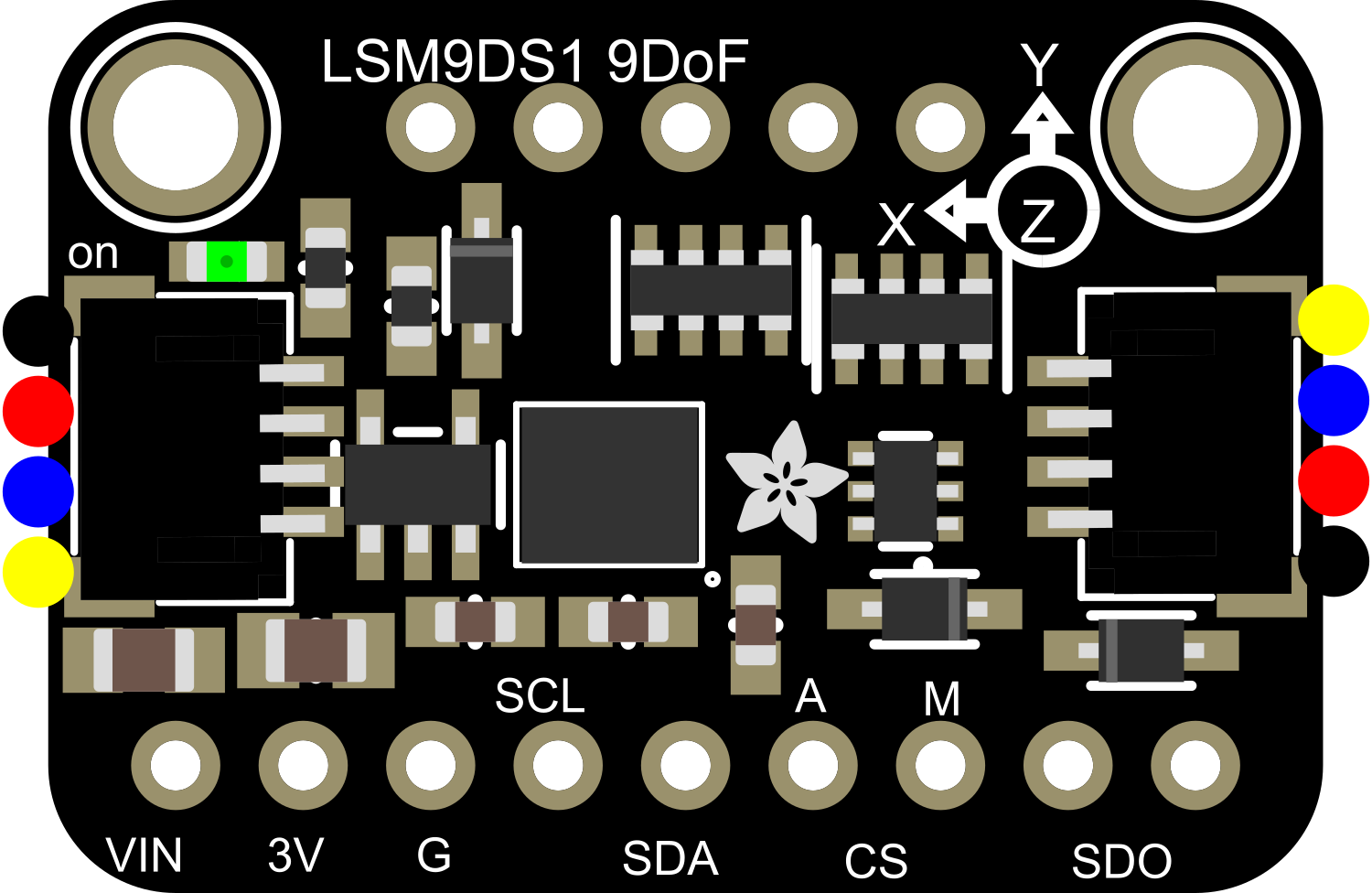
Pin Configuration and Descriptions

Pin Number Name Description
1 VIN Supply voltage input (2.4V to 3.6V)
2 3Vo 3.3V output from the voltage regulator
3 GND Ground connection
4 SCL I2C clock (also SPI SCL)
5 SDA I2C data (also SPI SDA)
6 SDO/SA0 SPI data output (also I2C SA0)
7 CSAG Chip select for the accelerometer and gyroscope
8 CSM Chip select for the magnetometer
9 SDA1 Secondary I2C data (for Stemma QT connector)
10 SCL1 Secondary I2C clock (for Stemma QT connector)

Usage Instructions

Integration into a Circuit

To use the LSM9DS1 breakout in a circuit:

  1. Connect VIN to a 2.4V to 3.6V power supply.
  2. Connect GND to the ground of your power supply.
  3. For I2C communication, connect SCL to the I2C clock and SDA to the I2C data lines. If using SPI, connect the respective SPI pins.
  4. If using I2C, ensure that the SDO/SA0 pin is correctly configured to set the I2C address.
  5. For SPI, connect CSAG and CSM to your microcontroller's chip select pins.

Best Practices

  • Use pull-up resistors on the I2C lines if they are not already present on your microcontroller board.
  • Ensure that the power supply is stable and within the specified voltage range.
  • When using SPI, ensure that the chip select lines are correctly managed to avoid communication conflicts.

Example Code for Arduino UNO

Below is an example of how to interface the LSM9DS1 with an Arduino UNO using I2C:

#include <Wire.h>
#include <Adafruit_Sensor.h>
#include <Adafruit_LSM9DS1.h>

// Create an instance of the LSM9DS1 class
Adafruit_LSM9DS1 lsm = Adafruit_LSM9DS1();

void setup() {
  Serial.begin(115200);
  
  // Initialize the sensor
  if (!lsm.begin()) {
    Serial.println("Failed to initialize LSM9DS1. Check your wiring!");
    while (1);
  }
  
  // Configure the sensor
  lsm.setupAccel(lsm.LSM9DS1_ACCELRANGE_2G);
  lsm.setupMag(lsm.LSM9DS1_MAGGAIN_4GAUSS);
  lsm.setupGyro(lsm.LSM9DS1_GYROSCALE_245DPS);
}

void loop() {
  // Read the sensor
  lsm.read();
  
  // Print accelerometer data
  Serial.print("Accel X: "); Serial.print(lsm.accelData.x); Serial.print(" ");
  Serial.print("Y: "); Serial.print(lsm.accelData.y); Serial.print(" ");
  Serial.print("Z: "); Serial.println(lsm.accelData.z);
  
  // Print gyroscope data
  Serial.print("Gyro X: "); Serial.print(lsm.gyroData.x); Serial.print(" ");
  Serial.print("Y: "); Serial.print(lsm.gyroData.y); Serial.print(" ");
  Serial.print("Z: "); Serial.println(lsm.gyroData.z);
  
  // Print magnetometer data
  Serial.print("Mag X: "); Serial.print(lsm.magData.x); Serial.print(" ");
  Serial.print("Y: "); Serial.print(lsm.magData.y); Serial.print(" ");
  Serial.print("Z: "); Serial.println(lsm.magData.z);
  
  // Delay before the next reading
  delay(1000);
}

This code initializes the LSM9DS1 sensor and configures its accelerometer, magnetometer, and gyroscope with basic settings. It then reads the sensor data and prints it to the Serial Monitor.

Troubleshooting and FAQs

Common Issues

  • Sensor not detected: Ensure that the wiring is correct, and the power supply is within the specified range. Check the I2C address if using I2C communication.
  • Inaccurate readings: Calibrate the sensor as per the datasheet instructions and ensure that there are no magnetic interferences nearby.
  • No data on Serial Monitor: Confirm that the correct baud rate is set in the Serial Monitor and that the Arduino board is connected to the correct COM port.

FAQs

Q: Can I use this sensor with a 5V microcontroller? A: Yes, but ensure that the logic level for the I2C or SPI communication is within the sensor's specified range (1.8V to 3.6V).

Q: How do I change the I2C address? A: The I2C address can be changed by connecting the SDO/SA0 pin to either ground or VDD.

Q: Can I use multiple LSM9DS1 sensors on the same I2C bus? A: Yes, you can use multiple sensors by assigning different I2C addresses to each sensor using the SDO/SA0 pin.

For further assistance, consult the Adafruit LSM9DS1 datasheet and the Adafruit support forums.