How to Use EMI Filter: Examples, Pinouts, and Specs
Introduction
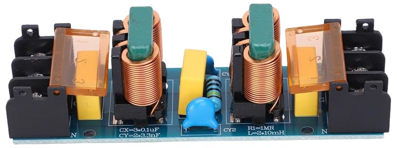
An EMI (Electromagnetic Interference) Filter is a device designed to suppress electromagnetic interference in electrical circuits. It ensures that signals remain clear and reduces noise that can degrade the performance of electronic systems. EMI filters are commonly used in power supplies, communication systems, and industrial equipment to maintain signal integrity and comply with electromagnetic compatibility (EMC) standards.
Explore Projects Built with EMI Filter
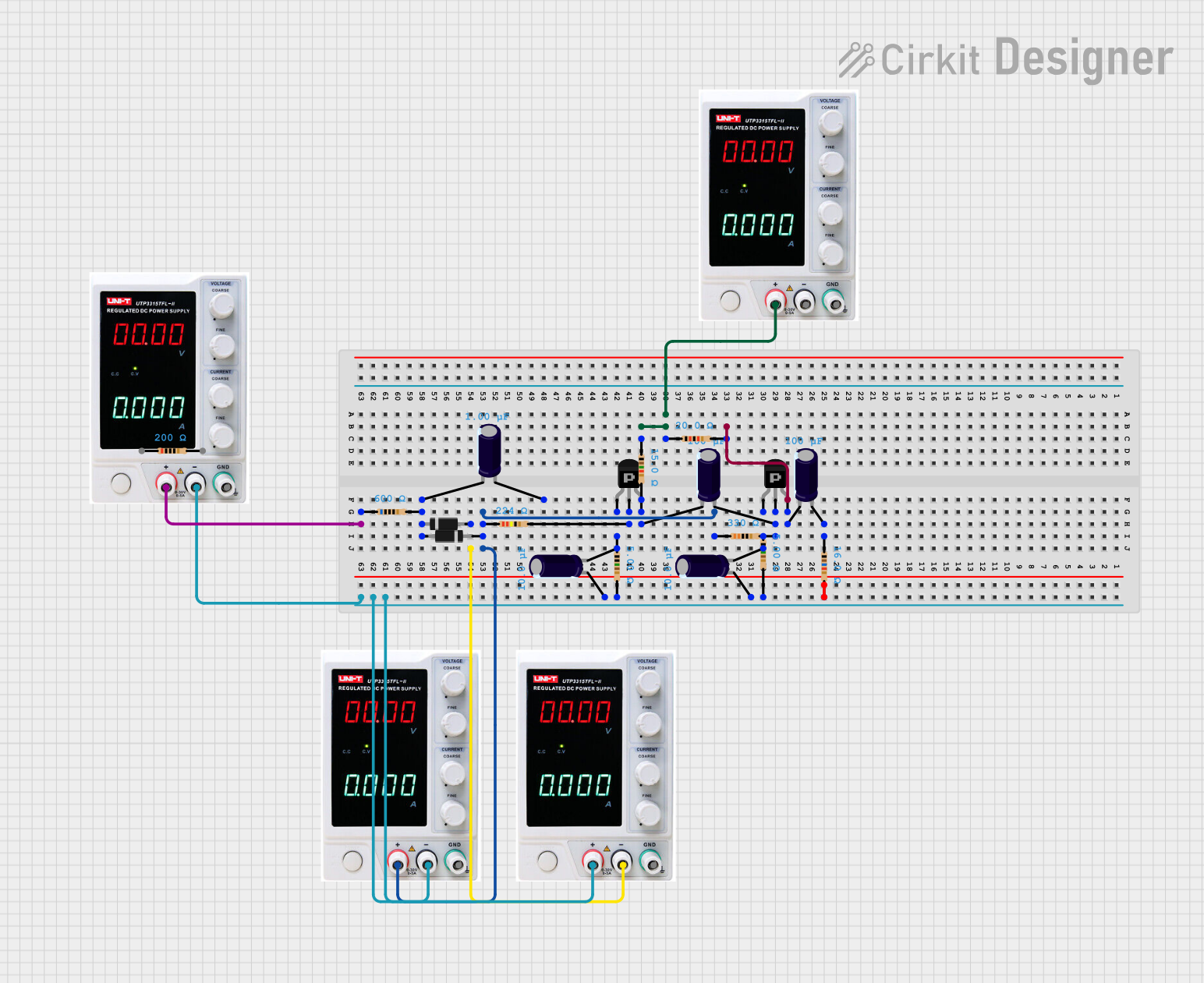


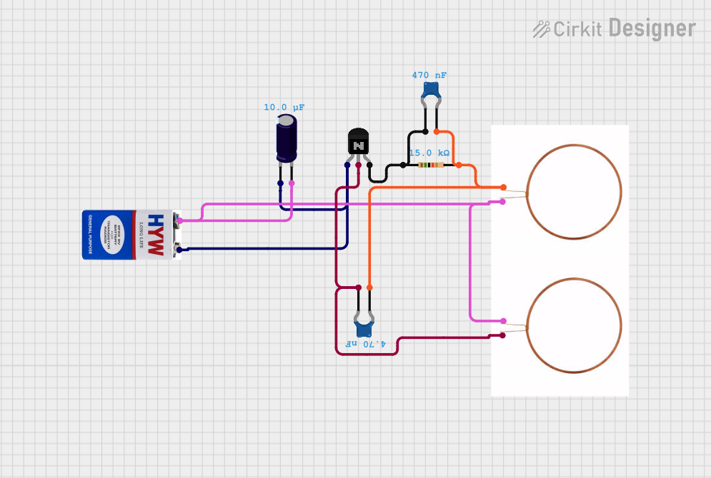
Explore Projects Built with EMI Filter
Common Applications and Use Cases
- Power supply circuits to reduce conducted and radiated noise
- Industrial equipment to meet EMC compliance
- Communication systems to prevent signal distortion
- Consumer electronics to improve performance and reliability
- Automotive systems to suppress interference from motors and other components
Technical Specifications
Key Technical Details
| Parameter | Value/Range |
|---|---|
| Operating Voltage | 5V to 250V AC/DC (varies by model) |
| Current Rating | 0.5A to 50A (depending on application) |
| Frequency Range | 50 Hz to 1 GHz |
| Insertion Loss | 10 dB to 100 dB |
| Operating Temperature | -25°C to +85°C |
| Compliance Standards | IEC, FCC, CISPR, MIL-STD |
Pin Configuration and Descriptions
The pin configuration of an EMI filter depends on its type (e.g., single-phase or three-phase). Below is an example for a single-phase EMI filter:
| Pin Number | Label | Description |
|---|---|---|
| 1 | Line (L) | Input live wire connection |
| 2 | Neutral (N) | Input neutral wire connection |
| 3 | Ground (G) | Ground connection for safety |
| 4 | Line Out | Output live wire connection |
| 5 | Neutral Out | Output neutral wire connection |
For three-phase EMI filters, additional pins for the three phases (L1, L2, L3) are included.
Usage Instructions
How to Use the Component in a Circuit
- Identify the Input and Output Connections: Connect the input terminals (Line and Neutral) of the EMI filter to the power source. Connect the output terminals to the load (e.g., a power supply or electronic device).
- Grounding: Ensure the ground pin is properly connected to the system ground to enhance safety and improve filtering performance.
- Placement: Place the EMI filter as close as possible to the power source or the device it is protecting to minimize noise propagation.
- Orientation: Follow the manufacturer's guidelines for proper orientation to ensure optimal performance.
Important Considerations and Best Practices
- Voltage and Current Ratings: Ensure the EMI filter's voltage and current ratings match or exceed the requirements of your circuit.
- Frequency Range: Select an EMI filter with a frequency range that covers the noise frequencies in your application.
- Compliance: Verify that the EMI filter meets the necessary EMC standards for your region or industry.
- Shielding: Use additional shielding if the EMI filter alone does not sufficiently suppress interference.
- Testing: Test the circuit with and without the EMI filter to confirm its effectiveness in reducing noise.
Example: Using an EMI Filter with an Arduino UNO
When using an EMI filter to suppress noise in an Arduino-based project, connect the filter between the power source and the Arduino's power input. Below is an example of Arduino code to monitor a sensor, ensuring the EMI filter reduces noise interference:
// Example Arduino code to read a sensor value and print it to the Serial Monitor
// Ensure the EMI filter is properly installed to reduce noise in the circuit

const int sensorPin = A0; // Analog pin connected to the sensor
int sensorValue = 0;      // Variable to store the sensor reading

void setup() {
  Serial.begin(9600); // Initialize serial communication at 9600 baud
}

void loop() {
  sensorValue = analogRead(sensorPin); // Read the sensor value
  Serial.print("Sensor Value: ");
  Serial.println(sensorValue); // Print the sensor value to the Serial Monitor
  delay(500); // Wait for 500 milliseconds before the next reading
}
Troubleshooting and FAQs
Common Issues Users Might Face
Excessive Noise After Installation:
- Cause: Incorrect grounding or improper filter placement.
- Solution: Verify that the ground connection is secure and the filter is installed close to the noise source.
Overheating of the EMI Filter:
- Cause: Exceeding the voltage or current rating of the filter.
- Solution: Use an EMI filter with appropriate ratings for your application.
Reduced Filtering Performance:
- Cause: Mismatched frequency range or improper orientation.
- Solution: Ensure the filter's frequency range matches the noise frequencies and follow the manufacturer's installation guidelines.
Intermittent Operation:
- Cause: Loose connections or damaged filter components.
- Solution: Check all connections and replace the filter if necessary.
FAQs
Q1: Can an EMI filter eliminate all noise in a circuit?
A1: No, an EMI filter reduces noise within its specified frequency range. Additional measures, such as shielding or grounding, may be required for complete noise suppression.
Q2: How do I choose the right EMI filter for my application?
A2: Consider the operating voltage, current rating, frequency range, and compliance standards. Consult the manufacturer's datasheet for detailed specifications.
Q3: Can I use an EMI filter with DC circuits?
A3: Yes, EMI filters are available for both AC and DC circuits. Ensure the filter is designed for your specific application.
Q4: Do EMI filters require maintenance?
A4: EMI filters are generally maintenance-free. However, periodic inspections for physical damage or loose connections are recommended.
Q5: Can I use multiple EMI filters in a single circuit?
A5: Yes, multiple filters can be used if necessary, but ensure they are properly configured to avoid impedance mismatches or reduced performance.