Cirkit Designer Logo
Cirkit Designer
Your all-in-one circuit design IDE
Home / 
Component Documentation

How to Use MASSIVE RC V2: Examples, Pinouts, and Specs

Image of MASSIVE RC V2
Cirkit Designer LogoDesign with MASSIVE RC V2 in Cirkit Designer

Introduction

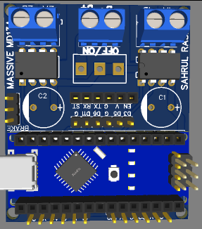
The MASSIVE RC V2 is a high-performance remote control system designed for precise and reliable control of various electronic devices. Manufactured by Massive, this component features advanced signal processing and robust connectivity options, making it ideal for a wide range of applications.

Explore Projects Built with MASSIVE RC V2

Use Cirkit Designer to design, explore, and prototype these projects online. Some projects support real-time simulation. Click "Open Project" to start designing instantly!
Battery-Powered RC Car with Massive RC MDEx and MDD10A Motor Driver
Image of Massive RC MDEx: A project utilizing MASSIVE RC V2 in a practical application
This circuit is a remote-controlled motor driver system powered by a LiPo battery. It uses a Massive RC MDEx microcontroller to control an MDD10A dual motor driver, which in turn drives two GM25 DC motors. The R6FG receiver receives remote control signals to manage the motor directions and speeds.
Cirkit Designer LogoOpen Project in Cirkit Designer
RC Receiver and Brushless Motor Control System with Battery-Powered Servo Motors
Image of Avion Poly: A project utilizing MASSIVE RC V2 in a practical application
This circuit is designed for a remote-controlled system, featuring an RC receiver that controls multiple servo motors and a brushless motor via an electronic speed controller (ESC). The RC receiver channels are connected to the PWM inputs of the servos and the signal input of the ESC, which in turn drives the brushless motor. Power is supplied by a LiPo battery, which also powers the RC receiver and servos through the ESC.
Cirkit Designer LogoOpen Project in Cirkit Designer
Battery-Powered Remote-Controlled Dual Motor System with Cytron URC10
Image of URC10 SUMO RC: A project utilizing MASSIVE RC V2 in a practical application
This circuit is a remote-controlled dual DC motor driver system powered by a 3S LiPo battery. It uses a Cytron URC10 motor driver to control two GM25 DC motors based on signals received from an R6FG receiver, with a rocker switch for power control and a 7-segment panel voltmeter for monitoring the battery voltage.
Cirkit Designer LogoOpen Project in Cirkit Designer
Battery-Powered Line Following Robot with IR Sensors and Cytron URC10 Motor Controller
Image of URC10 SUMO AUTO: A project utilizing MASSIVE RC V2 in a practical application
This circuit is a robotic control system that uses multiple IR sensors for line detection and obstacle avoidance, powered by a 3S LiPo battery. The Cytron URC10 motor driver, controlled by a microcontroller, drives two GM25 DC motors based on input from the sensors and a rocker switch, with a 7-segment panel voltmeter displaying the battery voltage.
Cirkit Designer LogoOpen Project in Cirkit Designer

Explore Projects Built with MASSIVE RC V2

Use Cirkit Designer to design, explore, and prototype these projects online. Some projects support real-time simulation. Click "Open Project" to start designing instantly!
Image of Massive RC MDEx: A project utilizing MASSIVE RC V2 in a practical application
Battery-Powered RC Car with Massive RC MDEx and MDD10A Motor Driver
This circuit is a remote-controlled motor driver system powered by a LiPo battery. It uses a Massive RC MDEx microcontroller to control an MDD10A dual motor driver, which in turn drives two GM25 DC motors. The R6FG receiver receives remote control signals to manage the motor directions and speeds.
Cirkit Designer LogoOpen Project in Cirkit Designer
Image of Avion Poly: A project utilizing MASSIVE RC V2 in a practical application
RC Receiver and Brushless Motor Control System with Battery-Powered Servo Motors
This circuit is designed for a remote-controlled system, featuring an RC receiver that controls multiple servo motors and a brushless motor via an electronic speed controller (ESC). The RC receiver channels are connected to the PWM inputs of the servos and the signal input of the ESC, which in turn drives the brushless motor. Power is supplied by a LiPo battery, which also powers the RC receiver and servos through the ESC.
Cirkit Designer LogoOpen Project in Cirkit Designer
Image of URC10 SUMO RC: A project utilizing MASSIVE RC V2 in a practical application
Battery-Powered Remote-Controlled Dual Motor System with Cytron URC10
This circuit is a remote-controlled dual DC motor driver system powered by a 3S LiPo battery. It uses a Cytron URC10 motor driver to control two GM25 DC motors based on signals received from an R6FG receiver, with a rocker switch for power control and a 7-segment panel voltmeter for monitoring the battery voltage.
Cirkit Designer LogoOpen Project in Cirkit Designer
Image of URC10 SUMO AUTO: A project utilizing MASSIVE RC V2 in a practical application
Battery-Powered Line Following Robot with IR Sensors and Cytron URC10 Motor Controller
This circuit is a robotic control system that uses multiple IR sensors for line detection and obstacle avoidance, powered by a 3S LiPo battery. The Cytron URC10 motor driver, controlled by a microcontroller, drives two GM25 DC motors based on input from the sensors and a rocker switch, with a 7-segment panel voltmeter displaying the battery voltage.
Cirkit Designer LogoOpen Project in Cirkit Designer

Common Applications and Use Cases

  • Robotics: Control of robotic arms, drones, and other automated systems.
  • Home Automation: Remote control of lights, fans, and other household appliances.
  • Industrial Automation: Management of machinery and equipment in industrial settings.
  • RC Vehicles: Operation of remote-controlled cars, boats, and aircraft.

Technical Specifications

Key Technical Details

Parameter Value
Operating Voltage 3.3V - 5V
Operating Current 20mA
Signal Frequency 2.4 GHz
Range Up to 100 meters
Channels 6
Dimensions 50mm x 30mm x 10mm
Weight 15 grams

Pin Configuration and Descriptions

Pin Number Pin Name Description
1 VCC Power supply (3.3V - 5V)
2 GND Ground
3 CH1 Channel 1 signal output
4 CH2 Channel 2 signal output
5 CH3 Channel 3 signal output
6 CH4 Channel 4 signal output
7 CH5 Channel 5 signal output
8 CH6 Channel 6 signal output
9 ANT Antenna connection for signal transmission

Usage Instructions

How to Use the Component in a Circuit

  1. Power Supply: Connect the VCC pin to a 3.3V or 5V power source and the GND pin to the ground of your circuit.
  2. Signal Outputs: Connect the CH1 to CH6 pins to the respective control inputs of the devices you wish to control.
  3. Antenna: Attach an appropriate antenna to the ANT pin to ensure robust signal transmission.

Important Considerations and Best Practices

  • Power Supply: Ensure that the power supply voltage is within the specified range (3.3V - 5V) to avoid damaging the component.
  • Signal Interference: Keep the antenna away from other electronic components to minimize signal interference.
  • Heat Dissipation: Ensure proper ventilation around the component to prevent overheating during prolonged use.

Example: Connecting to an Arduino UNO

Below is an example of how to connect the MASSIVE RC V2 to an Arduino UNO and control an LED using one of the channels.

Circuit Diagram

  1. Connect the VCC pin of the MASSIVE RC V2 to the 5V pin of the Arduino UNO.
  2. Connect the GND pin of the MASSIVE RC V2 to the GND pin of the Arduino UNO.
  3. Connect the CH1 pin of the MASSIVE RC V2 to digital pin 9 of the Arduino UNO.
  4. Connect an LED to digital pin 9 of the Arduino UNO with a current-limiting resistor.

Arduino Code

// MASSIVE RC V2 Example Code
// This code demonstrates how to control an LED using the MASSIVE RC V2
// connected to an Arduino UNO.

const int ledPin = 9; // Pin connected to CH1 of MASSIVE RC V2

void setup() {
  pinMode(ledPin, OUTPUT); // Set the LED pin as an output
  Serial.begin(9600); // Initialize serial communication
}

void loop() {
  int signal = pulseIn(ledPin, HIGH); // Read the signal from CH1
  if (signal > 1500) { // If signal is high, turn on the LED
    digitalWrite(ledPin, HIGH);
  } else { // If signal is low, turn off the LED
    digitalWrite(ledPin, LOW);
  }
  delay(100); // Small delay for stability
}

Troubleshooting and FAQs

Common Issues Users Might Face

  1. No Signal Reception:

    • Solution: Ensure the antenna is properly connected and there are no obstructions between the transmitter and receiver.
  2. Component Overheating:

    • Solution: Check the power supply voltage and ensure it is within the specified range. Provide adequate ventilation.
  3. Interference with Other Devices:

    • Solution: Change the operating frequency or relocate the component to minimize interference.

FAQs

Q1: Can I use the MASSIVE RC V2 with a 12V power supply?

  • A1: No, the operating voltage range is 3.3V to 5V. Using a 12V power supply may damage the component.

Q2: What is the maximum range of the MASSIVE RC V2?

  • A2: The maximum range is up to 100 meters in an open area without obstructions.

Q3: How many devices can I control with the MASSIVE RC V2?

  • A3: You can control up to 6 devices using the 6 available channels.

Q4: Can I use the MASSIVE RC V2 for wireless data transmission?

  • A4: The MASSIVE RC V2 is primarily designed for remote control applications. For wireless data transmission, consider using a dedicated data transmission module.

This documentation provides a comprehensive guide to using the MASSIVE RC V2 remote control system. Whether you are a beginner or an experienced user, following these instructions and best practices will help you achieve reliable and precise control of your electronic devices.