
How to Use 12v 5 pin relay: Examples, Pinouts, and Specs
 Design with 12v 5 pin relay in Cirkit Designer
Introduction
The 12V 5-pin relay is an electromechanical switch that uses an electromagnet to open or close a circuit. It is commonly used to control high-voltage or high-current devices, such as motors, lights, or appliances, using a low-voltage control signal. This makes it an essential component in automation, automotive systems, and home electronics.
Explore Projects Built with 12v 5 pin relay
 Open Project in Cirkit Designer
 Open Project in Cirkit Designer
 Open Project in Cirkit Designer
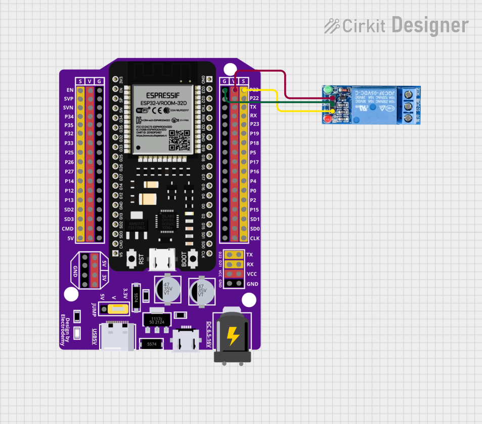 Open Project in Cirkit Designer
Explore Projects Built with 12v 5 pin relay
Open Project in Cirkit DesignerOpen Project in Cirkit DesignerOpen Project in Cirkit DesignerOpen Project in Cirkit DesignerCommon Applications
- Automotive systems (e.g., controlling headlights, horns, or fans)
- Home automation (e.g., switching appliances or lights)
- Industrial control systems
- Microcontroller-based projects (e.g., Arduino or Raspberry Pi)
Technical Specifications
The following table outlines the key technical details of the 12V 5-pin relay:
| Parameter | Value |
|---|---|
| Operating Voltage | 12V DC |
| Coil Resistance | ~400 Ohms |
| Switching Voltage | Up to 250V AC / 30V DC |
| Switching Current | Up to 10A |
| Contact Configuration | SPDT (Single Pole Double Throw) |
| Dimensions | ~28mm x 28mm x 25mm |
| Weight | ~20g |
| Insulation Resistance | ≥100MΩ |
| Dielectric Strength | 500V AC (coil to contact) |
Pin Configuration
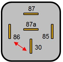
The 12V 5-pin relay has the following pinout:
| Pin Number | Name | Description |
|---|---|---|
| 1 | Coil (+) | Positive terminal of the relay coil (12V input) |
| 2 | Coil (-) | Negative terminal of the relay coil (GND) |
| 3 | Common (COM) | Common terminal for the switching contacts |
| 4 | Normally Open (NO) | Connected to COM when the relay is activated |
| 5 | Normally Closed (NC) | Connected to COM when the relay is inactive |
Usage Instructions
How to Use the 12V 5-Pin Relay in a Circuit
- Power the Relay Coil: Connect the coil pins (1 and 2) to a 12V DC power source. Pin 1 should be connected to the positive terminal, and Pin 2 to ground.
- Control the Load:
- Connect the load (e.g., a motor or light) to the COM (Pin 3) and either the NO (Pin 4) or NC (Pin 5) pin, depending on the desired behavior:
- Use NO if the load should be powered only when the relay is activated.
- Use NC if the load should be powered when the relay is inactive.
- Connect the load (e.g., a motor or light) to the COM (Pin 3) and either the NO (Pin 4) or NC (Pin 5) pin, depending on the desired behavior:
- Trigger the Relay: Apply a control signal (12V DC) to the coil pins to activate the relay. This will switch the connection between COM and NO.
Important Considerations
- Diode Protection: Always connect a flyback diode across the coil terminals to protect the circuit from voltage spikes when the relay is deactivated.
- Current Ratings: Ensure the load does not exceed the relay's maximum current rating (10A).
- Isolation: Use optocouplers or transistors to isolate the control circuit from the high-voltage load, especially when using microcontrollers.
Example: Connecting to an Arduino UNO
Below is an example of how to control a 12V 5-pin relay using an Arduino UNO:
Circuit Connections
- Connect the relay's Coil (+) to a 12V power supply.
- Connect the relay's Coil (-) to the collector of an NPN transistor (e.g., 2N2222).
- Connect the emitter of the transistor to ground.
- Connect a 1kΩ resistor between the Arduino digital pin (e.g., Pin 7) and the base of the transistor.
- Connect a flyback diode (e.g., 1N4007) across the relay coil terminals, with the cathode to Coil (+) and the anode to Coil (-).
Arduino Code
// Define the relay control pin
const int relayPin = 7;

void setup() {
  pinMode(relayPin, OUTPUT); // Set the relay pin as an output
  digitalWrite(relayPin, LOW); // Ensure the relay is off at startup
}

void loop() {
  digitalWrite(relayPin, HIGH); // Activate the relay
  delay(1000); // Keep the relay on for 1 second
  digitalWrite(relayPin, LOW); // Deactivate the relay
  delay(1000); // Keep the relay off for 1 second
}
Best Practices
- Use a separate power supply for the relay coil if the load requires high current.
- Avoid switching inductive loads (e.g., motors) without proper snubber circuits to prevent contact arcing.
- Test the relay with a multimeter before integrating it into your project.
Troubleshooting and FAQs
Common Issues
Relay Not Activating:
- Ensure the coil is receiving 12V DC.
- Check the transistor or control circuit for proper operation.
- Verify the flyback diode is installed correctly.
Load Not Switching:
- Confirm the load is connected to the correct pins (COM and NO/NC).
- Check for loose or faulty connections.
- Ensure the load does not exceed the relay's current rating.
Relay Buzzing or Clicking Rapidly:
- This may indicate insufficient voltage or current to the coil.
- Verify the power supply can provide adequate current for the relay.
FAQs
Q: Can I use the 12V 5-pin relay with a 5V control signal?
A: No, the relay requires a 12V DC signal to activate the coil. You can use a transistor or relay driver circuit to interface a 5V control signal with the relay.
Q: How do I know if the relay is working?
A: You should hear a clicking sound when the relay activates. You can also use a multimeter to check the continuity between COM and NO/NC.
Q: Can I use this relay for AC loads?
A: Yes, the relay can switch AC loads up to 250V, but ensure the load current does not exceed 10A.
By following this documentation, you can effectively integrate the 12V 5-pin relay into your projects and troubleshoot common issues.