Cirkit Designer Logo
Cirkit Designer
Your all-in-one circuit design IDE
Home / 
Component Documentation

How to Use TLP281 4-Channel Opto-isolator IC Module: Examples, Pinouts, and Specs

Image of TLP281 4-Channel Opto-isolator IC Module
Cirkit Designer LogoDesign with TLP281 4-Channel Opto-isolator IC Module in Cirkit Designer

Introduction

The TLP281 is a 4-channel opto-isolator that provides electrical isolation between its input and output. It consists of an LED on the input side and a phototransistor on the output side, enabling signal transmission while maintaining electrical isolation. This feature makes the TLP281 ideal for protecting sensitive low-voltage circuits from high-voltage systems or noisy environments.

Explore Projects Built with TLP281 4-Channel Opto-isolator IC Module

Use Cirkit Designer to design, explore, and prototype these projects online. Some projects support real-time simulation. Click "Open Project" to start designing instantly!
ESP32-Based Industrial Control System with RS485 Communication and I2C Interface
Image of DRIVER TESTER : A project utilizing TLP281 4-Channel Opto-isolator IC Module in a practical application
This circuit integrates a microcontroller with a display, digital potentiometer, IO expander, and opto-isolator board for signal interfacing and isolation. It includes a UART to RS485 converter for serial communication and a power converter to step down voltage for the system. The circuit is designed for control and communication in an isolated and protected environment.
Cirkit Designer LogoOpen Project in Cirkit Designer
Cellular-Connected ESP32-CAM with Real-Time Clock and Isolated Control
Image of LRCM PHASE 2 PRO: A project utilizing TLP281 4-Channel Opto-isolator IC Module in a practical application
This circuit integrates a LilyGo-SIM7000G module with an RTC DS3231 for timekeeping, interfaced via I2C (SCL and SDA lines). An 8-Channel OPTO-COUPLER is used to isolate and interface external signals with the LilyGo-SIM7000G's GPIOs. Power is managed by a Buck converter, which steps down voltage from a DC Power Source to supply the ESP32-CAM and LilyGo-SIM7000G modules, as well as the OPTO-COUPLER.
Cirkit Designer LogoOpen Project in Cirkit Designer
ESP32-Based Wi-Fi Controlled 24V Input/Output Interface Module
Image of ESP32 4 på rad: A project utilizing TLP281 4-Channel Opto-isolator IC Module in a practical application
This circuit uses an ESP32 microcontroller to interface with a 3.3V PNP to 24V NPN photoelectric isolation module, which in turn connects to a 40-pin connector for general-purpose input and output. The 24V power supply provides the necessary voltage for the isolation module and the 40-pin connector, enabling the ESP32 to control and monitor high-voltage signals safely.
Cirkit Designer LogoOpen Project in Cirkit Designer
Cellular-Enabled IoT Device with Real-Time Clock and Power Management
Image of LRCM PHASE 2 BASIC: A project utilizing TLP281 4-Channel Opto-isolator IC Module in a practical application
This circuit features a LilyGo-SIM7000G module for cellular communication and GPS functionality, interfaced with an RTC DS3231 for real-time clock capabilities. It includes voltage sensing through two voltage sensor modules, and uses an 8-channel opto-coupler for isolating different parts of the circuit. Power management is handled by a buck converter connected to a DC power source and batteries, with a fuse for protection and a rocker switch for on/off control. Additionally, there's an LED for indication purposes.
Cirkit Designer LogoOpen Project in Cirkit Designer

Explore Projects Built with TLP281 4-Channel Opto-isolator IC Module

Use Cirkit Designer to design, explore, and prototype these projects online. Some projects support real-time simulation. Click "Open Project" to start designing instantly!
Image of DRIVER TESTER : A project utilizing TLP281 4-Channel Opto-isolator IC Module in a practical application
ESP32-Based Industrial Control System with RS485 Communication and I2C Interface
This circuit integrates a microcontroller with a display, digital potentiometer, IO expander, and opto-isolator board for signal interfacing and isolation. It includes a UART to RS485 converter for serial communication and a power converter to step down voltage for the system. The circuit is designed for control and communication in an isolated and protected environment.
Cirkit Designer LogoOpen Project in Cirkit Designer
Image of LRCM PHASE 2 PRO: A project utilizing TLP281 4-Channel Opto-isolator IC Module in a practical application
Cellular-Connected ESP32-CAM with Real-Time Clock and Isolated Control
This circuit integrates a LilyGo-SIM7000G module with an RTC DS3231 for timekeeping, interfaced via I2C (SCL and SDA lines). An 8-Channel OPTO-COUPLER is used to isolate and interface external signals with the LilyGo-SIM7000G's GPIOs. Power is managed by a Buck converter, which steps down voltage from a DC Power Source to supply the ESP32-CAM and LilyGo-SIM7000G modules, as well as the OPTO-COUPLER.
Cirkit Designer LogoOpen Project in Cirkit Designer
Image of ESP32 4 på rad: A project utilizing TLP281 4-Channel Opto-isolator IC Module in a practical application
ESP32-Based Wi-Fi Controlled 24V Input/Output Interface Module
This circuit uses an ESP32 microcontroller to interface with a 3.3V PNP to 24V NPN photoelectric isolation module, which in turn connects to a 40-pin connector for general-purpose input and output. The 24V power supply provides the necessary voltage for the isolation module and the 40-pin connector, enabling the ESP32 to control and monitor high-voltage signals safely.
Cirkit Designer LogoOpen Project in Cirkit Designer
Image of LRCM PHASE 2 BASIC: A project utilizing TLP281 4-Channel Opto-isolator IC Module in a practical application
Cellular-Enabled IoT Device with Real-Time Clock and Power Management
This circuit features a LilyGo-SIM7000G module for cellular communication and GPS functionality, interfaced with an RTC DS3231 for real-time clock capabilities. It includes voltage sensing through two voltage sensor modules, and uses an 8-channel opto-coupler for isolating different parts of the circuit. Power management is handled by a buck converter connected to a DC power source and batteries, with a fuse for protection and a rocker switch for on/off control. Additionally, there's an LED for indication purposes.
Cirkit Designer LogoOpen Project in Cirkit Designer

Common Applications and Use Cases

  • Microcontroller interfacing with high-voltage systems
  • Signal isolation in industrial automation
  • Noise suppression in communication systems
  • Protection of sensitive circuits from voltage spikes
  • Motor control and power supply circuits

Technical Specifications

Key Technical Details

  • Number of Channels: 4
  • Input LED Forward Voltage (Vf): 1.2V (typical), 1.4V (maximum)
  • Input LED Forward Current (If): 10mA (typical), 50mA (maximum)
  • Output Collector-Emitter Voltage (Vce): 80V (maximum)
  • Isolation Voltage: 2500Vrms (minimum)
  • Current Transfer Ratio (CTR): 50% to 600% (depending on If and Vce)
  • Operating Temperature Range: -25°C to +85°C
  • Package Type: DIP-16 or SOP-16 (depending on the module)

Pin Configuration and Descriptions

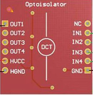
The TLP281 module typically has 16 pins, with 4 input channels and 4 output channels. Below is the pin configuration:

Pin Number Pin Name Description
1, 3, 5, 7 Anode (Input LED) Positive terminal of the input LED for channels 1, 2, 3, and 4, respectively.
2, 4, 6, 8 Cathode (Input LED) Negative terminal of the input LED for channels 1, 2, 3, and 4, respectively.
9, 11, 13, 15 Emitter (Output) Emitter terminal of the phototransistor for channels 1, 2, 3, and 4, respectively.
10, 12, 14, 16 Collector (Output) Collector terminal of the phototransistor for channels 1, 2, 3, and 4, respectively.

Usage Instructions

How to Use the TLP281 in a Circuit

  1. Input Side (LED):

    • Connect the anode of the input LED to a current-limiting resistor, which is then connected to the signal source (e.g., a microcontroller pin).
    • Connect the cathode of the input LED to ground.
    • Ensure the forward current (If) does not exceed the maximum rating (50mA).
  2. Output Side (Phototransistor):

    • Connect the collector of the phototransistor to the positive supply voltage (Vcc) through a pull-up resistor.
    • Connect the emitter of the phototransistor to ground.
    • The output signal can be read at the collector terminal. When the input LED is on, the phototransistor conducts, pulling the output low.
  3. Power Supply:

    • Ensure the module operates within the specified voltage and current limits.
    • Use decoupling capacitors near the power supply pins to reduce noise.

Important Considerations and Best Practices

  • Use appropriate current-limiting resistors to protect the input LEDs from excessive current.
  • Select a pull-up resistor value on the output side based on the desired signal speed and load requirements.
  • Avoid exceeding the maximum isolation voltage (2500Vrms) to prevent damage to the module.
  • Ensure proper grounding to maintain signal integrity and isolation.

Example: Connecting TLP281 to an Arduino UNO

Below is an example of how to connect one channel of the TLP281 to an Arduino UNO to control an external circuit:

Circuit Diagram

  • Input Side: Connect the anode of the input LED to an Arduino digital pin (e.g., D2) through a 220Ω resistor. Connect the cathode to ground.
  • Output Side: Connect the collector of the phototransistor to 5V through a 10kΩ pull-up resistor. Connect the emitter to ground. The output signal can be read at the collector.

Arduino Code

// Define the pin connected to the TLP281 input LED
const int optoInputPin = 2; // Arduino pin connected to the input LED

void setup() {
  pinMode(optoInputPin, OUTPUT); // Set the pin as an output
}

void loop() {
  digitalWrite(optoInputPin, HIGH); // Turn on the input LED
  delay(1000); // Wait for 1 second
  digitalWrite(optoInputPin, LOW);  // Turn off the input LED
  delay(1000); // Wait for 1 second
}

Troubleshooting and FAQs

Common Issues and Solutions

  1. No Output Signal:

    • Cause: Input LED not receiving sufficient current.
    • Solution: Check the current-limiting resistor value and ensure the input voltage is sufficient to drive the LED.
  2. Output Signal Always High:

    • Cause: Pull-up resistor missing or incorrect value.
    • Solution: Add a pull-up resistor to the collector terminal. Use a value between 1kΩ and 10kΩ based on the circuit requirements.
  3. Output Signal Always Low:

    • Cause: Input LED is always on or phototransistor is damaged.
    • Solution: Verify the input signal and ensure the LED is not continuously powered. Replace the module if necessary.
  4. Excessive Heat or Damage:

    • Cause: Exceeding voltage or current ratings.
    • Solution: Ensure all input and output parameters are within the specified limits.

FAQs

Q1: Can the TLP281 be used for AC signal isolation?
A1: Yes, the TLP281 can isolate AC signals, but additional circuitry (e.g., rectifiers) may be required to handle bidirectional signals.

Q2: What is the maximum switching speed of the TLP281?
A2: The TLP281 has a typical switching speed of a few microseconds, making it suitable for low- to medium-speed applications.

Q3: Can I use the TLP281 with a 3.3V microcontroller?
A3: Yes, the TLP281 can be used with 3.3V systems, but ensure the input LED receives sufficient forward current by adjusting the resistor value.

Q4: How do I calculate the current-limiting resistor for the input LED?
A4: Use the formula:
R = (Vsource - Vf) / If
Where Vsource is the input voltage, Vf is the forward voltage of the LED (1.2V typical), and If is the desired forward current (e.g., 10mA).