
How to Use EOG Sensor: Examples, Pinouts, and Specs
 Design with EOG Sensor in Cirkit Designer
Introduction
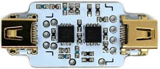
The EOG Sensor (Electrooculography Sensor) by BITalino is a specialized device designed to measure the electrical potential difference generated by eye movements and blinks. This sensor captures bioelectric signals from the muscles around the eyes, enabling applications in fields such as medical diagnostics, assistive technologies, and human-computer interaction.
Explore Projects Built with EOG Sensor
 Open Project in Cirkit Designer
 Open Project in Cirkit Designer
 Open Project in Cirkit Designer
 Open Project in Cirkit Designer
Explore Projects Built with EOG Sensor
Open Project in Cirkit DesignerOpen Project in Cirkit DesignerOpen Project in Cirkit DesignerOpen Project in Cirkit DesignerCommon Applications and Use Cases
- Medical Diagnostics: Monitoring eye movement disorders and neurological conditions.
- Assistive Technologies: Enabling eye-controlled interfaces for individuals with mobility impairments.
- Human-Computer Interaction: Eye-tracking for gaming, virtual reality, and research.
- Sleep Studies: Detecting rapid eye movement (REM) during sleep cycles.
- Robotics: Controlling robotic systems using eye gestures.
Technical Specifications
The following table outlines the key technical details of the BITalino EOG Sensor:
| Parameter | Specification |
|---|---|
| Manufacturer | BITalino |
| Part ID | EOG Sensor |
| Operating Voltage | 3.3V to 5V |
| Signal Bandwidth | 0.1 Hz to 100 Hz |
| Gain | 1100 |
| Input Impedance | >100 MΩ |
| Output Voltage Range | 0V to 3.3V (typical) |
| Connector Type | 3-pin interface (VCC, GND, Signal) |
| Dimensions | 25mm x 20mm x 5mm |
| Weight | 5 grams |
Pin Configuration and Descriptions
The EOG Sensor has a 3-pin interface for easy integration into circuits. The pin configuration is as follows:
| Pin | Name | Description |
|---|---|---|
| 1 | VCC | Power supply input (3.3V to 5V) |
| 2 | GND | Ground connection |
| 3 | Signal | Analog output signal representing eye movement data |
Usage Instructions
How to Use the EOG Sensor in a Circuit
- Power the Sensor: Connect the VCC pin to a 3.3V or 5V power source and the GND pin to the ground of your circuit.
- Signal Output: Connect the Signal pin to an analog input pin of a microcontroller (e.g., Arduino UNO) or an analog-to-digital converter (ADC).
- Electrode Placement: Use adhesive electrodes to capture bioelectric signals:
- Place one electrode near the outer corner of the eye (horizontal movement).
- Place another electrode above or below the eye (vertical movement).
- Use a reference electrode on a neutral location, such as the forehead.
- Signal Processing: The raw signal from the sensor may require filtering and amplification for accurate interpretation. Use software or external circuitry to process the data.
Important Considerations and Best Practices
- Electrode Quality: Ensure the electrodes are properly attached to the skin for reliable signal acquisition.
- Noise Reduction: Minimize electrical noise by keeping the sensor and electrodes away from power lines and other sources of interference.
- Calibration: Perform calibration to map the sensor's output to specific eye movements.
- Safety: Avoid using the sensor on broken or irritated skin.
Example: Connecting the EOG Sensor to an Arduino UNO
Below is an example Arduino sketch to read and display the EOG Sensor's output:
// EOG Sensor Example Code
// This code reads the analog signal from the EOG Sensor and prints it to the Serial Monitor.

const int EOG_PIN = A0; // Connect the Signal pin of the EOG Sensor to Arduino pin A0

void setup() {
  Serial.begin(9600); // Initialize serial communication at 9600 baud
  pinMode(EOG_PIN, INPUT); // Set the EOG pin as an input
}

void loop() {
  int eogValue = analogRead(EOG_PIN); // Read the analog value from the EOG Sensor
  Serial.print("EOG Signal: ");
  Serial.println(eogValue); // Print the value to the Serial Monitor
  delay(100); // Delay for 100ms to reduce data output frequency
}
Troubleshooting and FAQs
Common Issues and Solutions
No Signal Output:
- Ensure the sensor is powered correctly (check VCC and GND connections).
- Verify that the electrodes are properly attached and making good contact with the skin.
- Check the Signal pin connection to the microcontroller or ADC.
High Noise in Signal:
- Use shielded cables to reduce electromagnetic interference.
- Ensure the reference electrode is placed on a neutral location.
- Filter the signal using software or external circuitry (e.g., low-pass filter).
Weak or Inconsistent Signal:
- Replace worn-out or dried electrodes.
- Ensure the skin is clean and free of oils before attaching electrodes.
- Verify that the sensor is within its operating voltage range.
FAQs
Q: Can the EOG Sensor detect both horizontal and vertical eye movements?
A: Yes, by placing electrodes in appropriate positions, the sensor can detect both horizontal and vertical movements.
Q: Is the EOG Sensor compatible with microcontrollers other than Arduino?
A: Yes, the sensor outputs an analog signal, making it compatible with any microcontroller or ADC that supports analog input.
Q: How do I process the raw signal for specific applications?
A: Use signal processing techniques such as filtering, amplification, and feature extraction to interpret the data for your application.
Q: Can the sensor be used for long-term monitoring?
A: Yes, but ensure the electrodes are periodically replaced, and the skin is cleaned to maintain signal quality.
Q: Is the sensor safe for use on sensitive skin?
A: The sensor is generally safe, but avoid using it on broken or irritated skin to prevent discomfort.