Cirkit Designer Logo
Cirkit Designer
Your all-in-one circuit design IDE
Home / 
Component Documentation

How to Use HW-125: Examples, Pinouts, and Specs
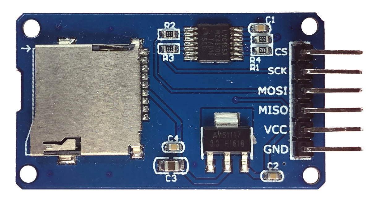
Image of HW-125
Cirkit Designer LogoDesign with HW-125 in Cirkit Designer

Introduction

The HW-125 is a compact heat sink designed for efficient heat dissipation from electronic components. Heat sinks are critical in managing the thermal performance of electronics, ensuring components operate within their temperature limits, thus prolonging their life and reliability. The HW-125 is commonly used with power transistors, voltage regulators, MOSFETs, and other heat-generating components in applications such as power supplies, amplifiers, and computing devices.

Explore Projects Built with HW-125
Use Cirkit Designer to design, explore, and prototype these projects online. Some projects support real-time simulation. Click "Open Project" to start designing instantly!
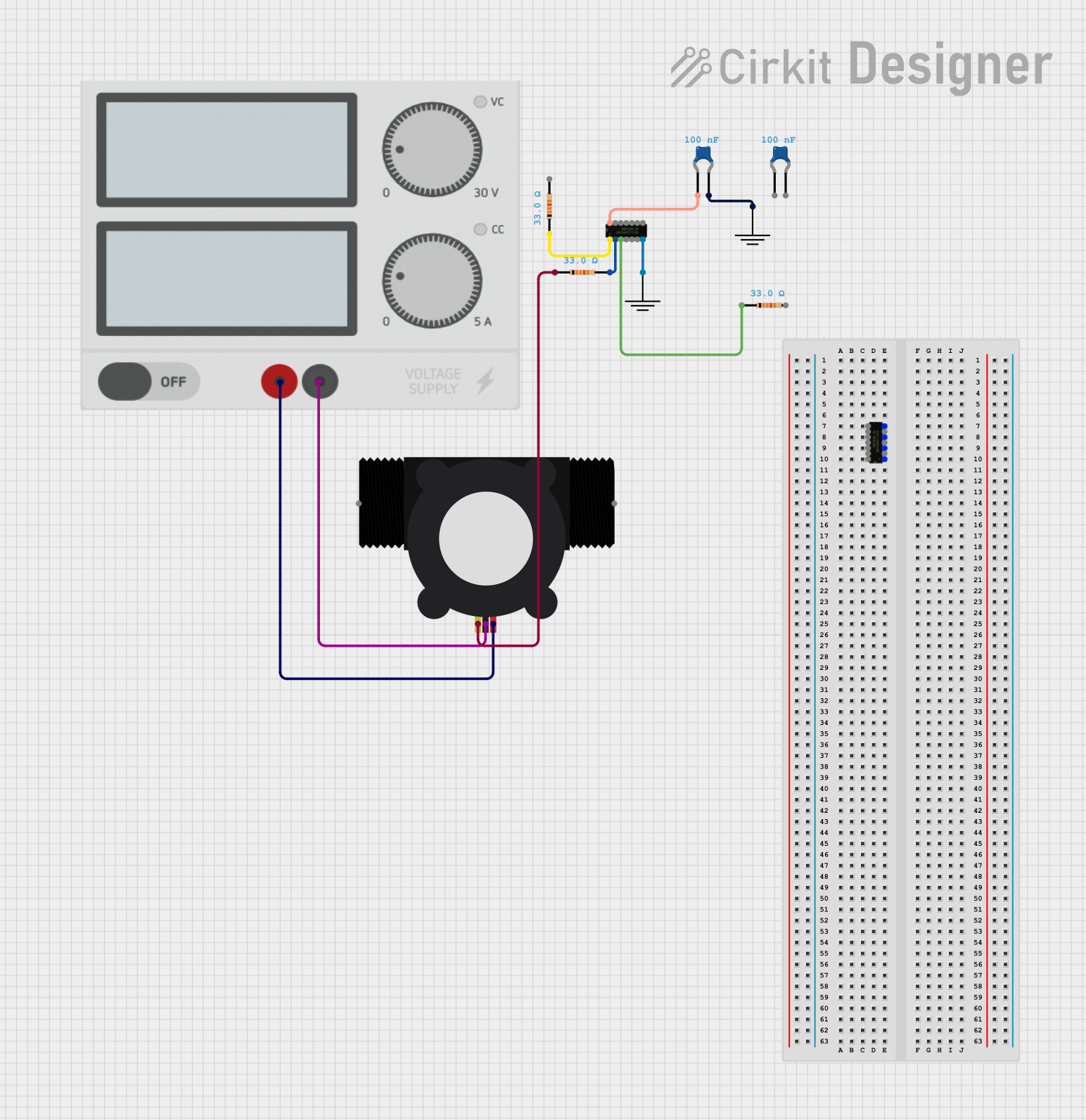
YF-S201 Water Flow Meter Interface with SN74AHCT125N Level Shifter
Image of Copy of flow: A project utilizing HW-125 in a practical application
This circuit is designed to interface a YF-S201 Water Flow Meter with an SN74AHCT125N buffer/level shifter, likely for signal conditioning purposes. The power supply provides the necessary voltage to the flow meter, and decoupling capacitors are used to stabilize the buffer's power supply. The circuit is prepared for further expansion or connection to a microcontroller for data processing, although no microcontroller or its code is included in the provided information.
Cirkit Designer LogoOpen Project in Cirkit Designer
Arduino UNO-Based Smart Irrigation System with Motion Detection and Bluetooth Connectivity
Image of Copy of wiring TA: A project utilizing HW-125 in a practical application
This circuit is a microcontroller-based control and monitoring system. It uses an Arduino UNO to read from a DHT22 temperature and humidity sensor and an HC-SR501 motion sensor, display data on an LCD, and control a water pump and an LED through a relay. The HC-05 Bluetooth module allows for wireless communication.
Cirkit Designer LogoOpen Project in Cirkit Designer
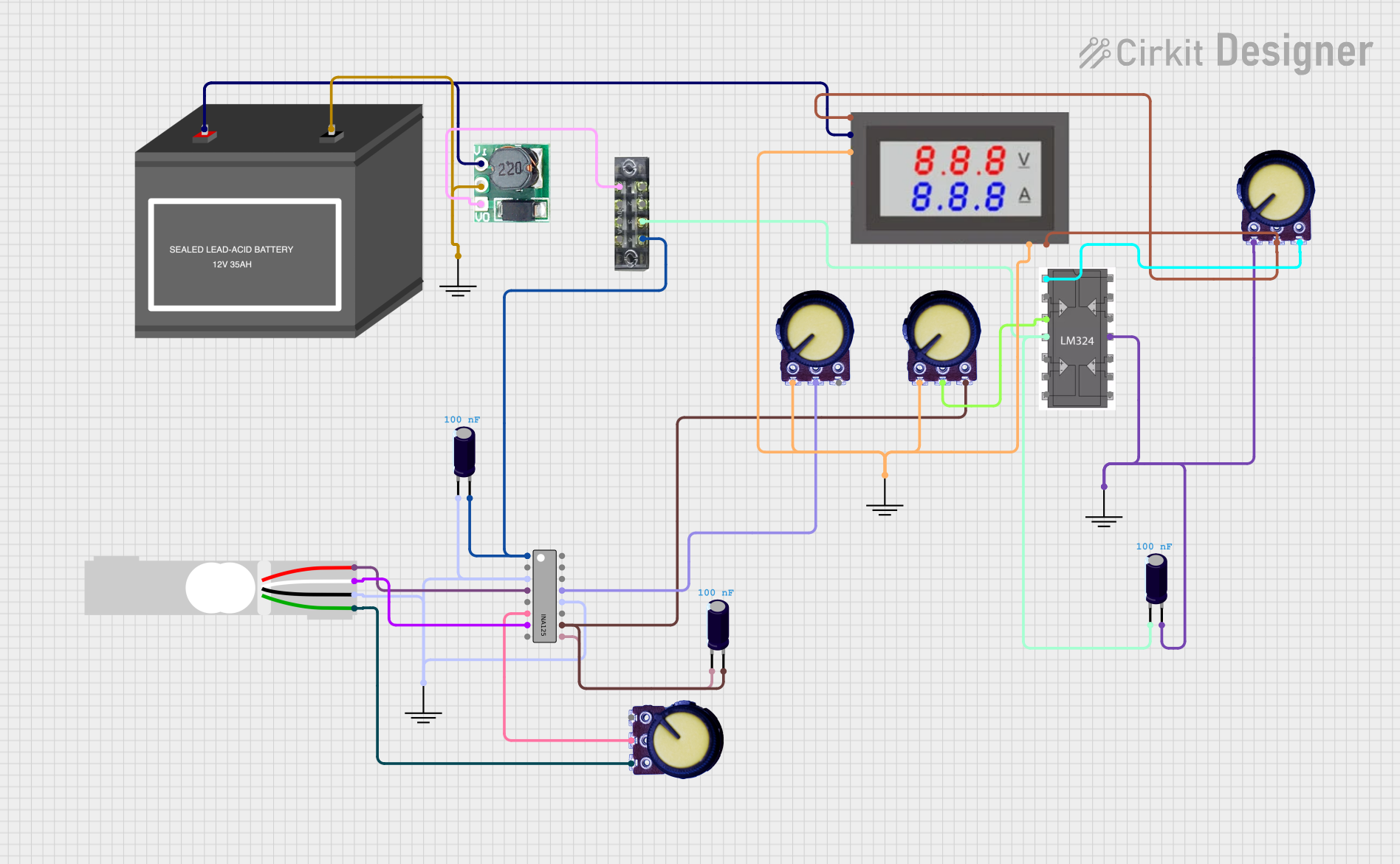
Battery-Powered Load Cell Amplifier with INA125 and LM324
Image of Test: A project utilizing HW-125 in a practical application
This circuit is a load cell signal conditioning and amplification system. It uses an INA125 instrumentation amplifier to amplify the differential signal from a load cell, with additional filtering and gain control provided by potentiometers and capacitors. The amplified signal is then monitored by a digital voltmeter, and the entire system is powered by a 12V battery with a step-up boost converter to provide stable voltage.
Cirkit Designer LogoOpen Project in Cirkit Designer
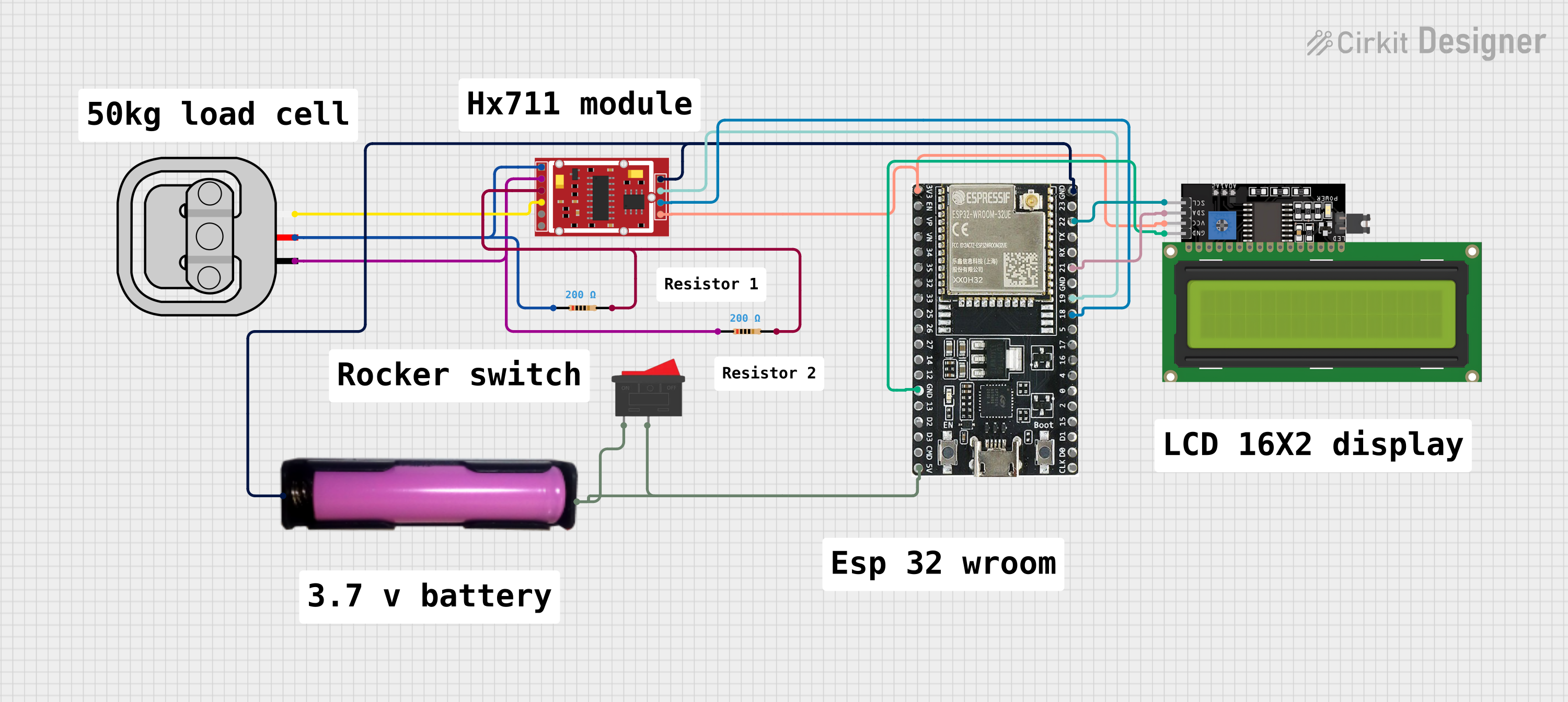
ESP32-Based Smart Weighing Scale with HX711 and LCD Display
Image of load cell: A project utilizing HW-125 in a practical application
This circuit is designed to measure weight using a 50kg load sensor interfaced with an HX711 weighing sensor module. The ESP32 microcontroller reads the measurements from the HX711 and displays the weight on an I2C-connected 16x4 LCD display. Power management is handled by a 18650 battery connected through a rocker switch, and two resistors are used for the load sensor's excitation and signal adjustment.
Cirkit Designer LogoOpen Project in Cirkit Designer

Explore Projects Built with HW-125

Use Cirkit Designer to design, explore, and prototype these projects online. Some projects support real-time simulation. Click "Open Project" to start designing instantly!
Image of Copy of flow: A project utilizing HW-125 in a practical application
YF-S201 Water Flow Meter Interface with SN74AHCT125N Level Shifter
This circuit is designed to interface a YF-S201 Water Flow Meter with an SN74AHCT125N buffer/level shifter, likely for signal conditioning purposes. The power supply provides the necessary voltage to the flow meter, and decoupling capacitors are used to stabilize the buffer's power supply. The circuit is prepared for further expansion or connection to a microcontroller for data processing, although no microcontroller or its code is included in the provided information.
Cirkit Designer LogoOpen Project in Cirkit Designer
Image of Copy of wiring TA: A project utilizing HW-125 in a practical application
Arduino UNO-Based Smart Irrigation System with Motion Detection and Bluetooth Connectivity
This circuit is a microcontroller-based control and monitoring system. It uses an Arduino UNO to read from a DHT22 temperature and humidity sensor and an HC-SR501 motion sensor, display data on an LCD, and control a water pump and an LED through a relay. The HC-05 Bluetooth module allows for wireless communication.
Cirkit Designer LogoOpen Project in Cirkit Designer
Image of Test: A project utilizing HW-125 in a practical application
Battery-Powered Load Cell Amplifier with INA125 and LM324
This circuit is a load cell signal conditioning and amplification system. It uses an INA125 instrumentation amplifier to amplify the differential signal from a load cell, with additional filtering and gain control provided by potentiometers and capacitors. The amplified signal is then monitored by a digital voltmeter, and the entire system is powered by a 12V battery with a step-up boost converter to provide stable voltage.
Cirkit Designer LogoOpen Project in Cirkit Designer
Image of load cell: A project utilizing HW-125 in a practical application
ESP32-Based Smart Weighing Scale with HX711 and LCD Display
This circuit is designed to measure weight using a 50kg load sensor interfaced with an HX711 weighing sensor module. The ESP32 microcontroller reads the measurements from the HX711 and displays the weight on an I2C-connected 16x4 LCD display. Power management is handled by a 18650 battery connected through a rocker switch, and two resistors are used for the load sensor's excitation and signal adjustment.
Cirkit Designer LogoOpen Project in Cirkit Designer

Technical Specifications

Key Technical Details

  • Material: Aluminum
  • Dimensions: 25mm x 34mm x 12mm (L x W x H)
  • Fin Design: Vertical orientation for optimal air flow
  • Mounting Method: Through-hole with screws or push pins
  • Thermal Resistance: Specific to application and airflow

Pin Configuration and Descriptions

The HW-125 does not have pins but is mounted directly to the component requiring heat dissipation. Below is a table describing the mounting specifications:

Feature Description
Mounting Hole Diameter suitable for M3 screws
Base Thickness Optimal thickness for thermal conduction
Fin Height Designed to maximize surface area within volume
Fin Spacing Allows sufficient airflow between fins

Usage Instructions

Mounting the HW-125 Heat Sink

  1. Component Preparation: Ensure the electronic component's surface is clean and free of debris.
  2. Thermal Interface Material (TIM): Apply a thin, even layer of thermal paste or a thermal pad to the component's surface to improve thermal conductivity.
  3. Alignment: Carefully align the HW-125 heat sink over the component, ensuring the mounting hole is positioned correctly.
  4. Securing the Heat Sink: Use appropriate M3 screws or push pins to secure the heat sink onto the component. Do not overtighten, as this may damage the component or the heat sink.
  5. Airflow: Ensure that there is adequate airflow around the heat sink fins. If necessary, use additional cooling measures such as fans.

Important Considerations and Best Practices

  • Thermal Paste Application: Too much thermal paste can insulate the component rather than transfer heat. Apply sparingly.
  • Orientation: Mount the heat sink in an orientation that aligns with the airflow direction within the enclosure for maximum cooling efficiency.
  • Inspection: Regularly inspect the heat sink for dust buildup, which can significantly reduce its cooling performance. Clean as necessary.

Troubleshooting and FAQs

Common Issues

  • Overheating: If the component is still overheating, check the thermal interface material for proper application and the airflow for obstructions.
  • Loose Heat Sink: A heat sink that is not securely attached can lead to poor thermal performance. Ensure it is mounted correctly.

Solutions and Tips

  • Reapply TIM: If overheating persists, remove the heat sink, clean off the old thermal paste, and apply a new layer.
  • Enhance Airflow: Consider adding a fan or improving the enclosure's ventilation to increase airflow over the heat sink.

FAQs

Q: Can the HW-125 be used with any component? A: The HW-125 is versatile but should be matched with components that fit its size and thermal dissipation capabilities.

Q: Is it necessary to use thermal paste? A: Yes, thermal paste or a thermal pad is crucial for filling microscopic gaps between the component and the heat sink, improving heat transfer.

Q: How do I clean the heat sink? A: Use compressed air to blow dust off the fins. For stubborn dirt, gently use a soft brush or cloth.

Note: This documentation is for the HW-125 heat sink, which is a passive electronic component and does not require electrical connection or Arduino code.