How to Use Dual 12V Motor Driver: Examples, Pinouts, and Specs
Introduction
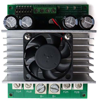
The Dual 12V Motor Driver is an electronic component designed to control two DC motors simultaneously. It provides the necessary voltage and current to drive motors operating at 12V, making it ideal for robotics, automation, and other motorized projects. This motor driver typically includes features such as direction control, speed regulation via PWM (Pulse Width Modulation), and protection mechanisms like overcurrent and thermal shutdown.
Explore Projects Built with Dual 12V Motor Driver


Explore Projects Built with Dual 12V Motor Driver
Common Applications
- Robotics (e.g., controlling wheels or robotic arms)
- Automated conveyor systems
- Remote-controlled vehicles
- DIY motorized projects
- Industrial automation systems
Technical Specifications
Below are the key technical details of the Dual 12V Motor Driver:
| Parameter | Value |
|---|---|
| Operating Voltage | 6V to 12V |
| Maximum Output Current | 2A per channel (continuous) |
| Peak Output Current | 3A per channel (short duration) |
| Control Logic Voltage | 3.3V or 5V (compatible with MCUs) |
| PWM Frequency Range | Up to 20 kHz |
| Motor Channels | 2 (independent control) |
| Protection Features | Overcurrent, thermal shutdown |
| Dimensions | Varies by model (e.g., 40x30mm) |
Pin Configuration and Descriptions
The Dual 12V Motor Driver typically has the following pin configuration:
Power and Motor Connections
| Pin Name | Description |
|---|---|
| VCC | Power supply input for the motors (6V-12V). |
| GND | Ground connection. |
| OUT1 | Output for Motor 1 positive terminal. |
| OUT2 | Output for Motor 1 negative terminal. |
| OUT3 | Output for Motor 2 positive terminal. |
| OUT4 | Output for Motor 2 negative terminal. |
Control Pins
| Pin Name | Description |
|---|---|
| IN1 | Control signal for Motor 1 direction (logic HIGH or LOW). |
| IN2 | Control signal for Motor 1 direction (logic HIGH or LOW). |
| IN3 | Control signal for Motor 2 direction (logic HIGH or LOW). |
| IN4 | Control signal for Motor 2 direction (logic HIGH or LOW). |
| ENA | PWM input for speed control of Motor 1. |
| ENB | PWM input for speed control of Motor 2. |
Usage Instructions
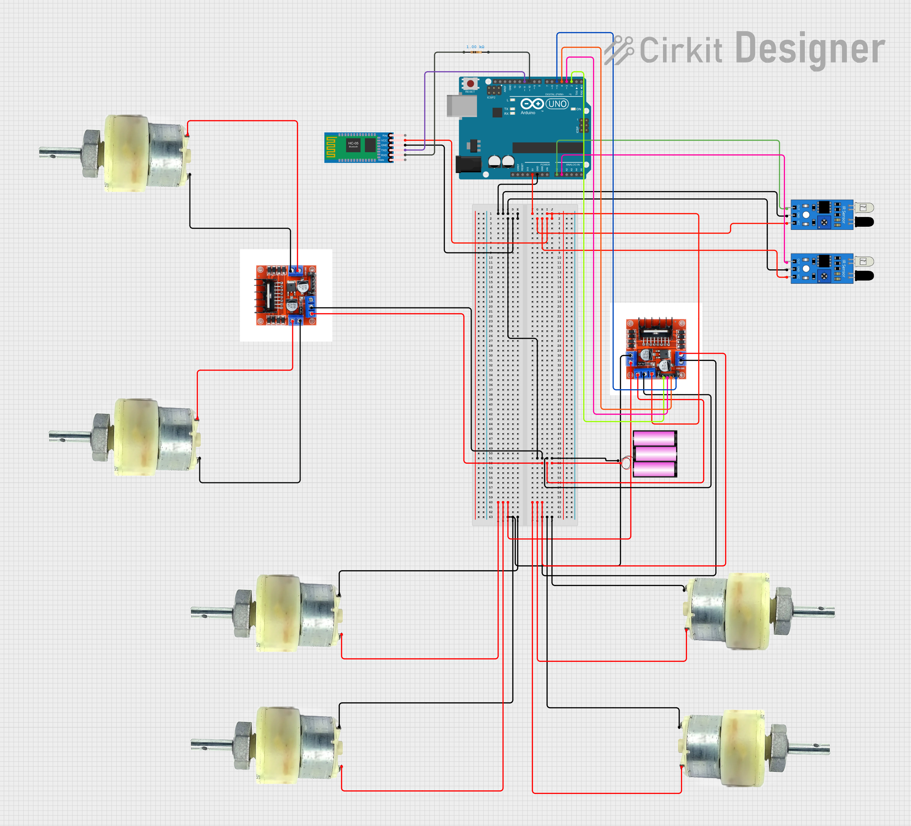
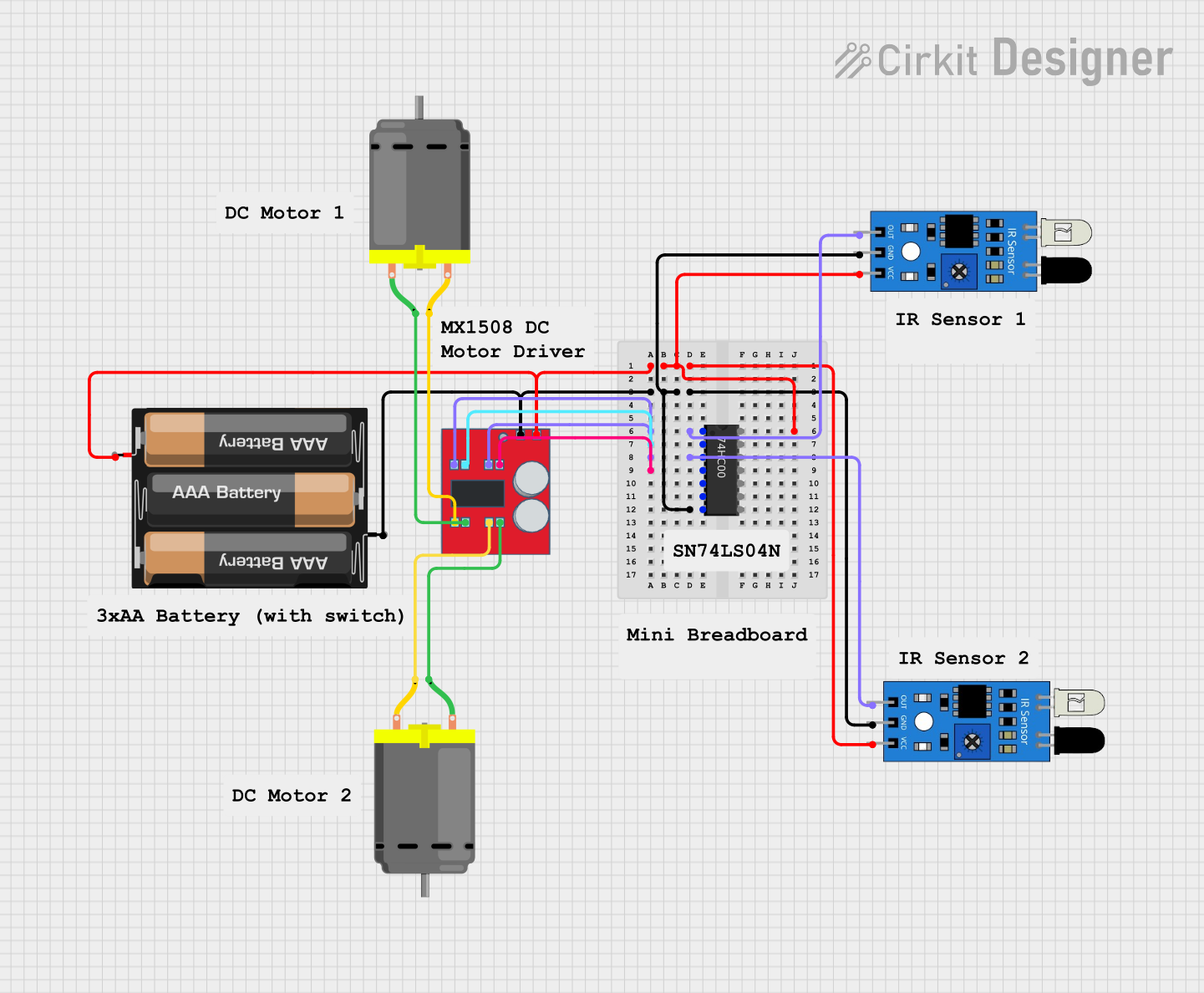
How to Use the Dual 12V Motor Driver in a Circuit
- Power Supply: Connect the VCC pin to a 12V power source and the GND pin to the ground of the power source.
- Motor Connections: Connect the DC motors to the output pins (OUT1, OUT2 for Motor 1 and OUT3, OUT4 for Motor 2).
- Control Signals: Use a microcontroller (e.g., Arduino UNO) to send control signals to the IN1, IN2, IN3, and IN4 pins for direction control.
- Speed Control: Provide PWM signals to the ENA and ENB pins to regulate the speed of Motor 1 and Motor 2, respectively.
Important Considerations
- Ensure the power supply voltage matches the motor's operating voltage (6V-12V).
- Do not exceed the maximum current rating (2A continuous, 3A peak per channel).
- Use appropriate heat dissipation methods if the driver operates at high currents for extended periods.
- Verify that the control logic voltage (3.3V or 5V) is compatible with your microcontroller.
Example Arduino Code
Below is an example of how to control two DC motors using an Arduino UNO and the Dual 12V Motor Driver:
// Define motor control pins
const int IN1 = 7;  // Motor 1 direction control pin
const int IN2 = 6;  // Motor 1 direction control pin
const int ENA = 5;  // Motor 1 speed control (PWM) pin
const int IN3 = 4;  // Motor 2 direction control pin
const int IN4 = 3;  // Motor 2 direction control pin
const int ENB = 2;  // Motor 2 speed control (PWM) pin

void setup() {
  // Set motor control pins as outputs
  pinMode(IN1, OUTPUT);
  pinMode(IN2, OUTPUT);
  pinMode(ENA, OUTPUT);
  pinMode(IN3, OUTPUT);
  pinMode(IN4, OUTPUT);
  pinMode(ENB, OUTPUT);
}

void loop() {
  // Motor 1: Forward at 50% speed
  digitalWrite(IN1, HIGH);  // Set direction
  digitalWrite(IN2, LOW);
  analogWrite(ENA, 128);    // Set speed (0-255)

  // Motor 2: Reverse at 75% speed
  digitalWrite(IN3, LOW);   // Set direction
  digitalWrite(IN4, HIGH);
  analogWrite(ENB, 192);    // Set speed (0-255)

  delay(2000);  // Run motors for 2 seconds

  // Stop both motors
  analogWrite(ENA, 0);
  analogWrite(ENB, 0);

  delay(2000);  // Wait for 2 seconds
}
Troubleshooting and FAQs
Common Issues and Solutions
Motors Not Running
- Cause: Incorrect wiring or loose connections.
- Solution: Double-check all connections, especially the power supply and motor terminals.
Motors Running in the Wrong Direction
- Cause: Control signals (IN1, IN2, IN3, IN4) are reversed.
- Solution: Swap the HIGH and LOW signals for the respective motor's control pins.
Overheating
- Cause: Exceeding the current rating or insufficient heat dissipation.
- Solution: Ensure the motor's current draw is within the driver's limits and add a heatsink if necessary.
PWM Speed Control Not Working
- Cause: Incorrect PWM signal or incompatible microcontroller.
- Solution: Verify the PWM frequency and ensure the microcontroller supports PWM on the specified pins.
FAQs
Q: Can I use this motor driver with a 24V motor?
A: No, the driver is designed for motors operating at 6V-12V. Using a 24V motor may damage the driver.
Q: How do I control the speed of the motors?
A: Use PWM signals on the ENA and ENB pins to adjust the motor speed. The duty cycle of the PWM signal determines the speed.
Q: Can I control stepper motors with this driver?
A: No, this driver is designed for DC motors. Stepper motors require a dedicated stepper motor driver.
Q: Is it compatible with Raspberry Pi?
A: Yes, as long as the control logic voltage (3.3V) matches the Raspberry Pi's GPIO output levels.