
How to Use Calliope Mini V 1.3: Examples, Pinouts, and Specs
 Design with Calliope Mini V 1.3 in Cirkit Designer
Introduction
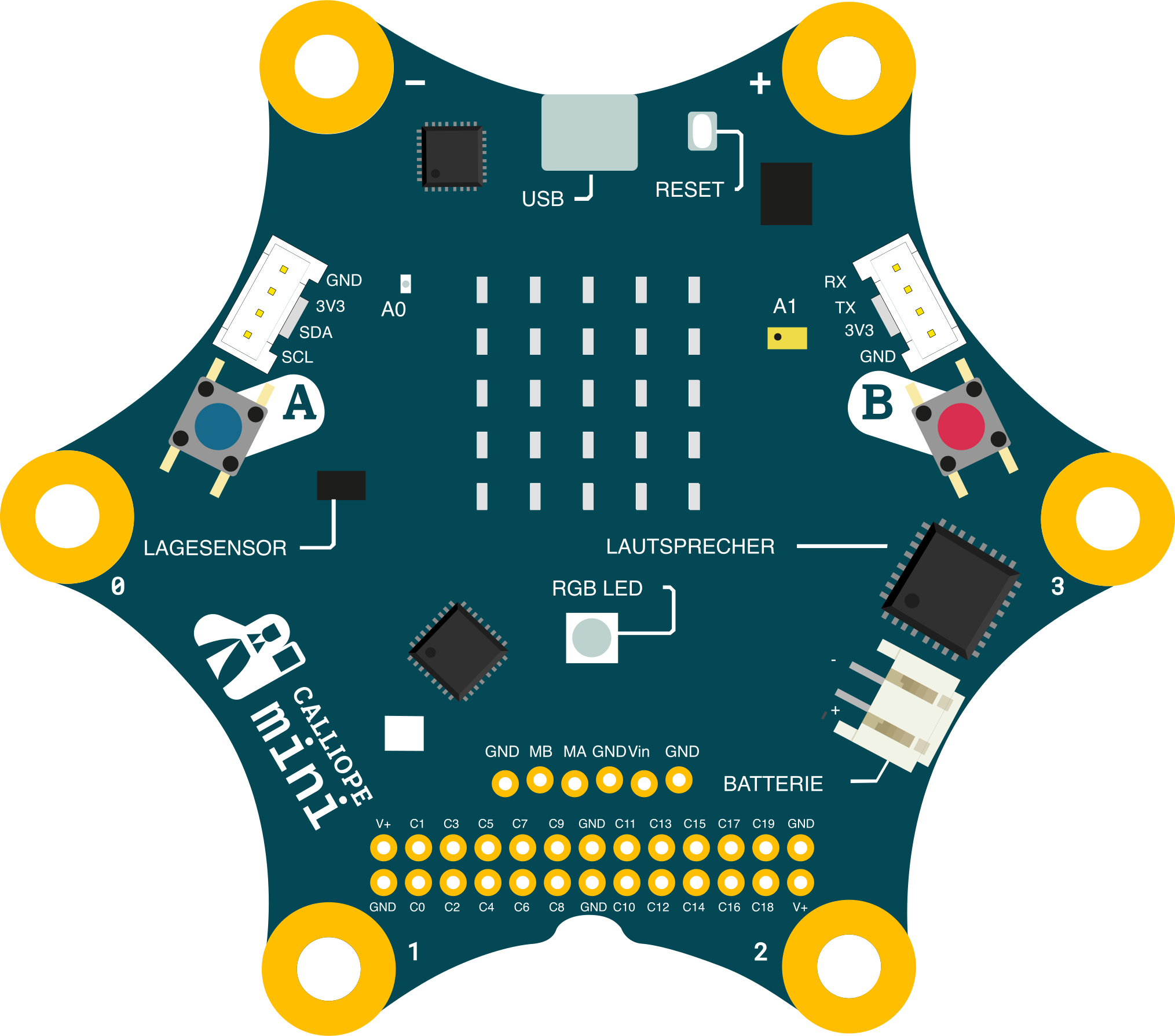
The Calliope Mini V 1.3 is a compact, programmable microcontroller board developed by Calliope. It is specifically designed for educational purposes, making it an excellent tool for teaching coding, electronics, and STEM concepts. The board features a variety of built-in sensors, LEDs, and connectivity options, enabling users to create interactive projects with ease. Its user-friendly design and versatility make it suitable for beginners and advanced users alike.
Explore Projects Built with Calliope Mini V 1.3
 Open Project in Cirkit Designer
 Open Project in Cirkit Designer
 Open Project in Cirkit Designer
 Open Project in Cirkit Designer
Explore Projects Built with Calliope Mini V 1.3
Open Project in Cirkit DesignerOpen Project in Cirkit DesignerOpen Project in Cirkit DesignerOpen Project in Cirkit DesignerCommon Applications and Use Cases
- Educational Projects: Ideal for teaching programming and electronics in schools.
- Interactive Prototyping: Create interactive devices using built-in sensors and LEDs.
- IoT Projects: Utilize Bluetooth connectivity for Internet of Things applications.
- Robotics: Control motors and servos for simple robotics projects.
- Wearable Technology: Lightweight and compact design makes it suitable for wearables.
Technical Specifications
Key Technical Details
| Specification | Details |
|---|---|
| Microcontroller | Nordic nRF51822 (ARM Cortex-M0, 16 MHz) |
| Flash Memory | 256 KB |
| RAM | 16 KB |
| Power Supply | 3V to 5V (via USB, battery pack, or coin cell battery) |
| Connectivity | Bluetooth Low Energy (BLE) |
| Sensors | Accelerometer, Magnetometer, Temperature Sensor, Microphone |
| Outputs | 25 programmable LEDs, 2 RGB LEDs, Piezo Speaker |
| Inputs | 2 programmable buttons, GPIO pins, touch-sensitive pins |
| Dimensions | 65 mm x 65 mm |
Pin Configuration and Descriptions
The Calliope Mini V 1.3 features a variety of pins for input/output operations. Below is the pin configuration:
| Pin | Type | Description |
|---|---|---|
| P0 | GPIO/Analog | General-purpose I/O pin, supports analog input. |
| P1 | GPIO/Analog | General-purpose I/O pin, supports analog input. |
| P2 | GPIO/Analog | General-purpose I/O pin, supports analog input. |
| P3 | GPIO | General-purpose I/O pin. |
| P4 | GPIO | General-purpose I/O pin. |
| P5 | Button A | Connected to Button A, can also be used as a GPIO pin. |
| P6 | GPIO | General-purpose I/O pin. |
| P7 | GPIO | General-purpose I/O pin. |
| P8 | GPIO | General-purpose I/O pin. |
| P9 | GPIO | General-purpose I/O pin. |
| P10 | GPIO | General-purpose I/O pin. |
| P11 | Button B | Connected to Button B, can also be used as a GPIO pin. |
| P12 | GPIO | General-purpose I/O pin. |
| P13 | GPIO | General-purpose I/O pin. |
| P14 | GPIO | General-purpose I/O pin. |
| P15 | GPIO | General-purpose I/O pin. |
| P16 | GPIO | General-purpose I/O pin. |
| P17 | GPIO | General-purpose I/O pin. |
| P18 | GPIO | General-purpose I/O pin. |
| P19 | GPIO | General-purpose I/O pin. |
| P20 | GPIO | General-purpose I/O pin. |
Usage Instructions
How to Use the Calliope Mini V 1.3 in a Circuit
Powering the Board:
- Connect the board to a computer via a micro-USB cable for power and programming.
- Alternatively, use a 3V coin cell battery or a battery pack for standalone operation.
Programming the Board:
- Use the MakeCode Editor or Open Roberta Lab for block-based programming.
- For advanced users, the board supports programming in Python or C++.
Connecting Components:
- Use the GPIO pins to connect external components like LEDs, sensors, or motors.
- The touch-sensitive pins can be used for simple input operations.
Using Built-in Features:
- Utilize the onboard sensors (e.g., accelerometer, magnetometer) for interactive projects.
- Control the 25 programmable LEDs for visual feedback or animations.
Important Considerations and Best Practices
- Voltage Levels: Ensure external components operate within the board's voltage range (3V to 5V).
- Avoid Short Circuits: Be cautious when connecting components to avoid damaging the board.
- Firmware Updates: Regularly update the firmware to access the latest features and bug fixes.
- Bluetooth Usage: When using Bluetooth, ensure the board is within range of the paired device.
Example Code for Arduino UNO Integration
Although the Calliope Mini is not directly compatible with Arduino UNO, it can communicate with Arduino boards via serial communication. Below is an example of how to send data from the Calliope Mini to an Arduino UNO:
Calliope Mini Code (MakeCode)
// Send accelerometer data via serial communication
basic.forever(function () {
    serial.writeValue("x", input.acceleration(Dimension.X))
    serial.writeValue("y", input.acceleration(Dimension.Y))
    serial.writeValue("z", input.acceleration(Dimension.Z))
    basic.pause(100) // Pause for 100ms between transmissions
})
Arduino UNO Code
void setup() {
  Serial.begin(9600); // Initialize serial communication at 9600 baud
}

void loop() {
  if (Serial.available() > 0) {
    // Read incoming data from Calliope Mini
    String data = Serial.readString();
    Serial.println(data); // Print the received data to the Serial Monitor
  }
}
Troubleshooting and FAQs
Common Issues and Solutions
Board Not Detected by Computer:
- Ensure the USB cable is properly connected and supports data transfer.
- Try using a different USB port or cable.
- Check if the board is in programming mode (press the reset button if necessary).
Program Not Running:
- Verify that the program was successfully uploaded to the board.
- Ensure the board is powered correctly.
- Check for syntax errors in the code.
Bluetooth Connection Issues:
- Ensure Bluetooth is enabled on the paired device.
- Keep the board within the recommended range (typically 10 meters).
- Restart the board and the paired device if the connection fails.
LEDs Not Responding:
- Check the code to ensure the correct pins are being addressed.
- Verify that the board is receiving sufficient power.
FAQs
Can I use the Calliope Mini with Raspberry Pi?
Yes, the Calliope Mini can communicate with Raspberry Pi via GPIO or Bluetooth.What programming languages are supported?
The board supports block-based programming (MakeCode, Open Roberta), Python, and C++.How do I reset the board?
Press the reset button located on the back of the board to restart it.Can I connect external sensors?
Yes, external sensors can be connected via the GPIO pins or I2C interface.
This documentation provides a comprehensive guide to using the Calliope Mini V 1.3. Whether you're a beginner or an experienced user, this microcontroller board offers endless possibilities for creative and educational projects.