How to Use OPTOCOUPLER 8 CH ISOLATION: Examples, Pinouts, and Specs
Introduction
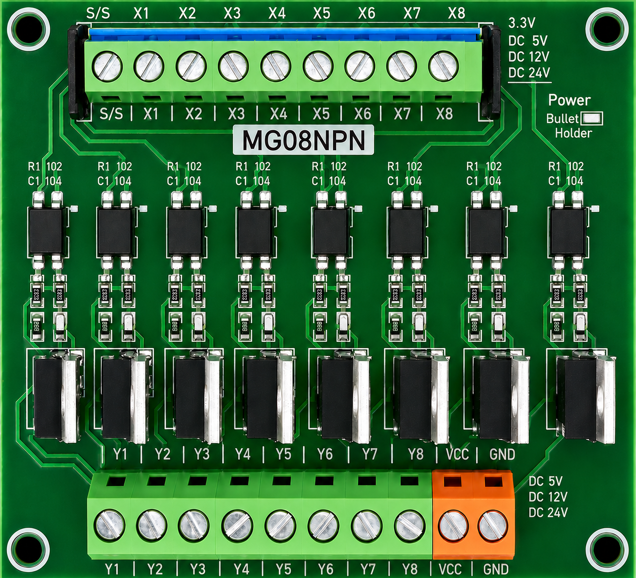
The OPTOCOUPLER 8 CH ISOLATION (Manufacturer Part ID: OPTO) is an 8-channel optocoupler module designed to provide electrical isolation between input and output signals. This isolation ensures that signals can be transmitted without direct electrical connection, protecting sensitive components from voltage spikes, noise, and ground loops. Manufactured by Signal Amplifier Board, this module is ideal for applications requiring reliable signal interfacing and protection.
Explore Projects Built with OPTOCOUPLER 8 CH ISOLATION


Explore Projects Built with OPTOCOUPLER 8 CH ISOLATION
Common Applications and Use Cases
- Digital signal interfacing between microcontrollers and high-voltage systems
- Protection of sensitive components from electrical noise and surges
- Isolation in industrial automation systems
- Signal transmission in motor control circuits
- Communication between systems with different ground potentials
Technical Specifications
Key Technical Details
| Parameter | Value |
|---|---|
| Number of Channels | 8 |
| Input Voltage Range | 3.3V to 24V |
| Output Voltage Range | 3.3V to 5V |
| Isolation Voltage | 2500V RMS |
| Input Current (per channel) | 5mA to 20mA |
| Output Type | Open-collector |
| Operating Temperature | -40°C to +85°C |
| Dimensions | 60mm x 40mm x 15mm |
Pin Configuration and Descriptions
The module has two sets of pins: Input Pins and Output Pins. Each channel has a corresponding input and output.
Input Pins
| Pin Number | Label | Description |
|---|---|---|
| 1-8 | IN1-IN8 | Input signal for channels 1 to 8 |
| 9 | VCC | Positive supply voltage (3.3V-24V) |
| 10 | GND | Ground connection |
Output Pins
| Pin Number | Label | Description |
|---|---|---|
| 1-8 | OUT1-OUT8 | Output signal for channels 1 to 8 |
| 9 | VCC | Positive supply voltage (3.3V-5V) |
| 10 | GND | Ground connection |
Usage Instructions
How to Use the Component in a Circuit
- Power the Module: Connect the input side's VCC and GND pins to a power source (3.3V to 24V). Similarly, connect the output side's VCC and GND pins to a separate power source (3.3V to 5V) if isolation is required.
- Connect Input Signals: Attach the input signals to the IN1-IN8 pins. Ensure the input voltage is within the specified range.
- Connect Output Signals: Connect the OUT1-OUT8 pins to the desired output circuit. These pins act as open-collector outputs and may require pull-up resistors.
- Verify Isolation: Ensure that the input and output grounds are not directly connected to maintain isolation.
Important Considerations and Best Practices
- Use pull-up resistors on the output pins if required by your circuit. A typical value is 10kΩ.
- Ensure the input current for each channel is within the specified range (5mA to 20mA).
- Avoid exceeding the isolation voltage rating (2500V RMS) to prevent damage.
- For Arduino or microcontroller applications, connect the output pins to digital input pins and configure them with pull-up resistors if necessary.
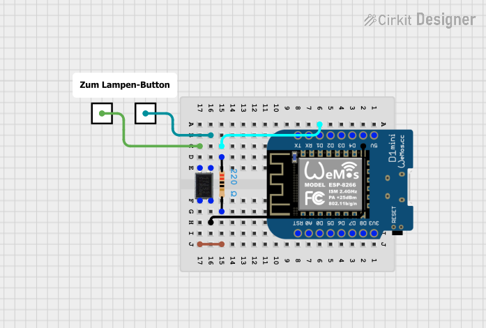
Example: Connecting to an Arduino UNO
Below is an example of how to connect the OPTOCOUPLER 8 CH ISOLATION module to an Arduino UNO to read input signals.
Circuit Connections
- Connect the module's input VCC and GND to a 5V power supply.
- Connect the module's output VCC and GND to the Arduino's 5V and GND pins.
- Connect OUT1-OUT8 to Arduino digital pins 2-9.
- Use pull-up resistors (10kΩ) on the output pins if needed.
Arduino Code Example
// Define input pins for the optocoupler module
const int optoPins[] = {2, 3, 4, 5, 6, 7, 8, 9}; // Arduino digital pins

void setup() {
  // Initialize serial communication for debugging
  Serial.begin(9600);

  // Configure optocoupler output pins as inputs
  for (int i = 0; i < 8; i++) {
    pinMode(optoPins[i], INPUT_PULLUP);
    // Use internal pull-up resistors to ensure stable readings
  }
}

void loop() {
  // Read and print the state of each optocoupler channel
  for (int i = 0; i < 8; i++) {
    int state = digitalRead(optoPins[i]); // Read the pin state
    Serial.print("Channel ");
    Serial.print(i + 1);
    Serial.print(": ");
    Serial.println(state == LOW ? "ON" : "OFF");
    // LOW indicates the optocoupler is active
  }
  delay(500); // Delay for readability
}
Troubleshooting and FAQs
Common Issues and Solutions
No Output Signal Detected
- Verify that the input signal voltage is within the specified range (3.3V to 24V).
- Check the pull-up resistors on the output pins. Without them, the output may not function correctly.
- Ensure the input and output grounds are not connected if isolation is required.
Output Signal is Unstable
- Use decoupling capacitors (e.g., 0.1µF) near the power supply pins to reduce noise.
- Ensure proper grounding and avoid long, unshielded wires for input and output connections.
Module Overheats
- Check that the input current does not exceed 20mA per channel.
- Verify that the input and output voltage levels are within the specified ranges.
FAQs
Q: Can I use this module with a 3.3V microcontroller?
A: Yes, the module supports 3.3V logic levels on both the input and output sides.
Q: Do I need external pull-up resistors?
A: Yes, if your circuit does not have internal pull-up resistors, you will need to add them to the output pins.
Q: Can I use this module for AC signal isolation?
A: No, this module is designed for DC signal isolation only. For AC signals, consider using a specialized optocoupler.
Q: What happens if I connect the input and output grounds?
A: Connecting the grounds will defeat the purpose of isolation and may introduce noise or ground loops into your circuit.
This concludes the documentation for the OPTOCOUPLER 8 CH ISOLATION module.