How to Use 2N4124: Examples, Pinouts, and Specs

Introduction
The 2N4124 is an N-channel MOSFET transistor designed for switching and amplification purposes in electronic circuits. It is known for its low on-resistance and high-speed operation, which makes it an excellent choice for applications requiring efficient power management and fast signal processing. This component is widely used in consumer electronics, industrial control systems, and communication devices.
Explore Projects Built with 2N4124
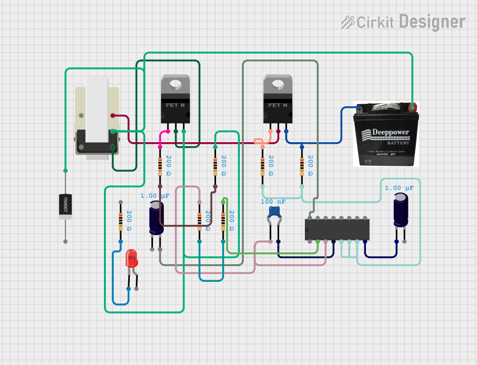


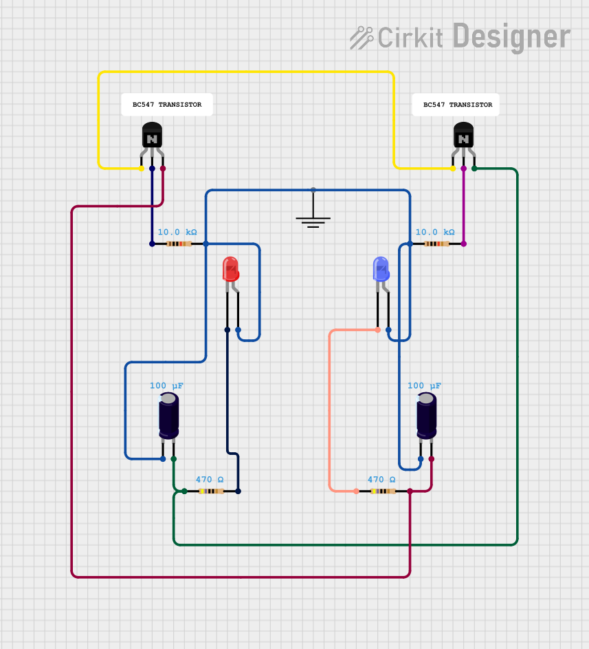
Explore Projects Built with 2N4124
Common Applications:
- Power management circuits
- Signal amplification
- Motor control
- Switching regulators
- Audio amplifiers
Technical Specifications
Below are the key technical details of the 2N4124 transistor:
| Parameter | Value |
|---|---|
| Transistor Type | N-channel MOSFET |
| Maximum Drain-Source Voltage (VDS) | 30V |
| Maximum Gate-Source Voltage (VGS) | ±20V |
| Continuous Drain Current (ID) | 200mA |
| Power Dissipation (PD) | 625mW |
| On-Resistance (RDS(on)) | 1.5Ω (typical) |
| Transition Frequency (fT) | 250MHz |
| Operating Temperature Range | -55°C to +150°C |
| Package Type | TO-92 |
Pin Configuration:
The 2N4124 is typically available in a TO-92 package with the following pinout:
| Pin Number | Pin Name | Description |
|---|---|---|
| 1 | Gate | Controls the transistor's operation |
| 2 | Drain | Current flows from drain to source |
| 3 | Source | Connected to ground or load |
Usage Instructions
How to Use the 2N4124 in a Circuit
- Basic Setup: Connect the source pin to ground or the negative terminal of the power supply. The drain pin should be connected to the load, and the gate pin should receive the control signal.
- Gate Voltage: Apply a voltage to the gate pin to turn the transistor on. Ensure the gate voltage does not exceed the maximum VGS rating of ±20V.
- Load Considerations: Ensure the load connected to the drain pin does not exceed the maximum current rating of 200mA.
- Heat Dissipation: If the transistor operates near its maximum power dissipation, consider adding a heatsink or improving ventilation to prevent overheating.
Example: Using the 2N4124 with an Arduino UNO
The following example demonstrates how to use the 2N4124 to control an LED with an Arduino UNO:
// Example: Controlling an LED with the 2N4124 and Arduino UNO
// Pin 9 is used as the control signal for the MOSFET gate.

const int mosfetGatePin = 9; // Arduino pin connected to the MOSFET gate
const int ledState = HIGH;  // Set to HIGH to turn on the LED

void setup() {
  pinMode(mosfetGatePin, OUTPUT); // Set the MOSFET gate pin as an output
}

void loop() {
  digitalWrite(mosfetGatePin, ledState); // Turn the LED on
  delay(1000);                           // Wait for 1 second
  digitalWrite(mosfetGatePin, LOW);      // Turn the LED off
  delay(1000);                           // Wait for 1 second
}
Best Practices:
- Use a resistor (e.g., 220Ω to 1kΩ) between the Arduino pin and the MOSFET gate to limit current and protect the microcontroller.
- Add a flyback diode across inductive loads (e.g., motors) to protect the MOSFET from voltage spikes.
- Ensure the MOSFET operates within its safe operating area (SOA) to avoid damage.
Troubleshooting and FAQs
Common Issues:
The transistor does not turn on:
- Ensure the gate voltage is sufficient to fully turn on the MOSFET.
- Check for loose or incorrect connections in the circuit.
The transistor overheats:
- Verify that the load current does not exceed the maximum rating of 200mA.
- Use a heatsink or improve ventilation if necessary.
The circuit does not work as expected:
- Double-check the pin connections (Gate, Drain, Source).
- Ensure the power supply voltage and current are within the transistor's specifications.
FAQs:
Q: Can the 2N4124 handle high-power loads?
A: No, the 2N4124 is designed for low-power applications with a maximum current rating of 200mA. For high-power loads, consider using a MOSFET with a higher current rating.
Q: Is the 2N4124 suitable for high-frequency switching?
A: Yes, the 2N4124 has a transition frequency of 250MHz, making it suitable for high-speed switching applications.
Q: Can I use the 2N4124 without a resistor on the gate?
A: While it is possible, it is recommended to use a resistor (220Ω to 1kΩ) to limit the inrush current and protect the control circuit.
By following the guidelines and best practices outlined in this documentation, you can effectively use the 2N4124 in your electronic projects.