How to Use 3S 10A Li-ion 18650 Charger Protection Board Module: Examples, Pinouts, and Specs
Introduction
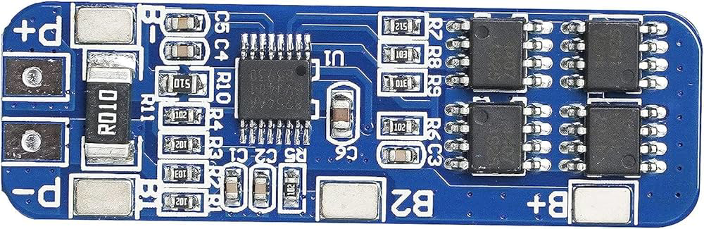
The 3S 10A Li-ion 18650 Charger Protection Board Module is a compact and efficient circuit designed to manage the charging and discharging of three 18650 lithium-ion cells connected in series. This module ensures the safety and longevity of the battery pack by providing essential protection features such as overcharge protection, over-discharge protection, and short-circuit protection. With a maximum current rating of 10A, it is suitable for a wide range of applications requiring reliable power management.
Explore Projects Built with 3S 10A Li-ion 18650 Charger Protection Board Module


Explore Projects Built with 3S 10A Li-ion 18650 Charger Protection Board Module
Common Applications and Use Cases
- Battery packs for portable devices
- DIY power banks
- Electric bicycles and scooters
- Solar energy storage systems
- Robotics and RC vehicles
Technical Specifications
Below are the key technical details of the 3S 10A Li-ion 18650 Charger Protection Board Module:
| Parameter | Value |
|---|---|
| Battery Configuration | 3S (3 cells in series) |
| Input Voltage Range | 12.6V (max) |
| Overcharge Protection Voltage | 4.25V ± 0.05V per cell |
| Over-discharge Protection Voltage | 2.8V ± 0.1V per cell |
| Maximum Continuous Current | 10A |
| Overcurrent Protection | 15A |
| Short-circuit Protection | Yes |
| Operating Temperature Range | -40°C to +85°C |
| Dimensions | ~50mm x 20mm x 3mm |
Pin Configuration and Descriptions
The module has several connection points for proper integration into a circuit. Below is the pin configuration:
| Pin Name | Description |
|---|---|
| B+ | Positive terminal of the battery pack |
| B- | Negative terminal of the battery pack |
| P+ | Positive terminal for load and charger |
| P- | Negative terminal for load and charger |
| BM | Connection point for the middle terminal of the battery pack (between cell 1 and cell 2) |
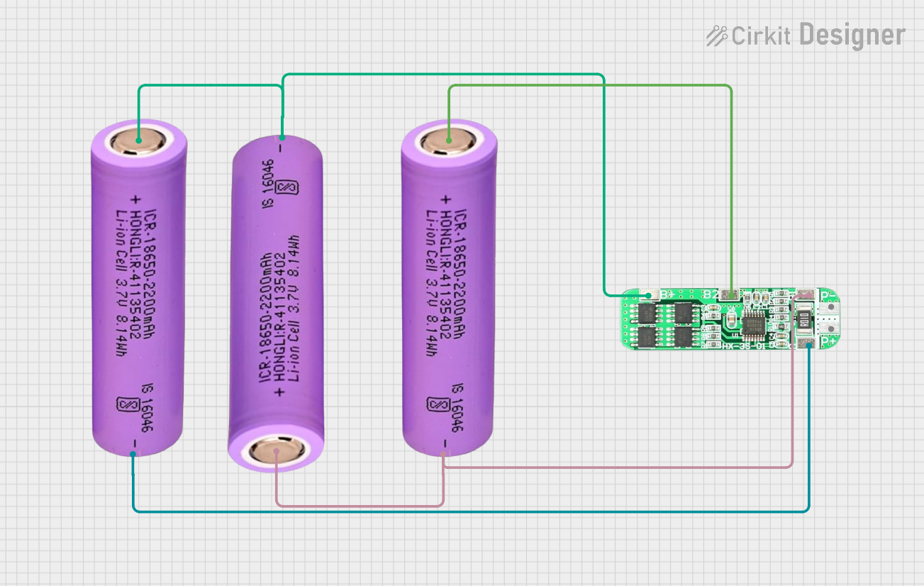
Usage Instructions
How to Use the Component in a Circuit
Connect the Battery Pack:
- Solder the positive terminal of the battery pack to the
B+pin. - Solder the negative terminal of the battery pack to the
B-pin. - Connect the middle terminal of the battery pack (between cell 1 and cell 2) to the
BMpin.
- Solder the positive terminal of the battery pack to the
Connect the Load and Charger:
- Solder the positive terminal of the load/charger to the
P+pin. - Solder the negative terminal of the load/charger to the
P-pin.
- Solder the positive terminal of the load/charger to the
Verify Connections:
- Double-check all connections to ensure proper polarity and secure soldering.
- Ensure the battery pack is balanced and cells are of the same capacity and charge level.
Power On:
- Once all connections are verified, the module will automatically manage charging and discharging operations.
Important Considerations and Best Practices
- Use only high-quality 18650 cells with matching capacities and charge levels.
- Avoid exceeding the maximum current rating of 10A to prevent damage to the module.
- Ensure proper heat dissipation if the module operates near its maximum current rating.
- Do not short-circuit the output terminals (
P+andP-). - Use a charger with a maximum output voltage of 12.6V to avoid overcharging the battery pack.
Arduino UNO Integration Example
While the 3S 10A Li-ion Charger Protection Board Module is not directly programmable, it can be monitored using an Arduino UNO to check battery voltage levels. Below is an example code to monitor the voltage of each cell:
// Arduino code to monitor the voltage of a 3S battery pack
// Connect the battery terminals to analog pins A0, A1, and A2 via voltage dividers

const int cell1Pin = A0; // Pin connected to the first cell's voltage divider
const int cell2Pin = A1; // Pin connected to the second cell's voltage divider
const int cell3Pin = A2; // Pin connected to the third cell's voltage divider

// Voltage divider resistors (adjust these values to match your circuit)
const float resistor1 = 10000.0; // Resistor connected to the battery
const float resistor2 = 10000.0; // Resistor connected to ground

void setup() {
  Serial.begin(9600); // Initialize serial communication
}

void loop() {
  // Read analog values and convert to voltage
  float cell1Voltage = analogRead(cell1Pin) * (5.0 / 1023.0) * ((resistor1 + resistor2) / resistor2);
  float cell2Voltage = analogRead(cell2Pin) * (5.0 / 1023.0) * ((resistor1 + resistor2) / resistor2);
  float cell3Voltage = analogRead(cell3Pin) * (5.0 / 1023.0) * ((resistor1 + resistor2) / resistor2);

  // Print the voltages to the Serial Monitor
  Serial.print("Cell 1 Voltage: ");
  Serial.print(cell1Voltage);
  Serial.println(" V");

  Serial.print("Cell 2 Voltage: ");
  Serial.print(cell2Voltage);
  Serial.println(" V");

  Serial.print("Cell 3 Voltage: ");
  Serial.print(cell3Voltage);
  Serial.println(" V");

  delay(1000); // Wait for 1 second before the next reading
}
Troubleshooting and FAQs
Common Issues and Solutions
Module Not Powering On:
- Cause: Incorrect wiring or loose connections.
- Solution: Verify all connections and ensure proper polarity.
Overheating During Operation:
- Cause: Exceeding the maximum current rating of 10A.
- Solution: Reduce the load current or improve heat dissipation.
Battery Pack Not Charging:
- Cause: Charger voltage is too low or connections are incorrect.
- Solution: Use a charger with a 12.6V output and verify connections.
Short-circuit Protection Triggered:
- Cause: Output terminals (
P+andP-) are shorted. - Solution: Remove the short circuit and reset the module by disconnecting and reconnecting the battery pack.
- Cause: Output terminals (
FAQs
Q: Can I use this module with fewer than three cells?
A: No, this module is specifically designed for a 3S configuration. Using fewer cells may result in improper operation or damage.
Q: What happens if one cell in the battery pack is damaged?
A: A damaged cell can cause imbalance and may trigger the protection features. Replace the damaged cell with a matching one.
Q: Can I use this module for LiFePO4 batteries?
A: No, this module is designed for lithium-ion batteries with a nominal voltage of 3.7V per cell. LiFePO4 batteries have different voltage characteristics.
Q: How do I reset the module after a short circuit?
A: Disconnect the battery pack and load, then reconnect them to reset the module.